Finally ... Repairing a traction gearbox.

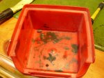
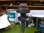
Gee's this stuff is brilliant.... Id never heard of speedie sleeves until Gerry mentioned them ...
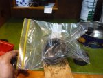
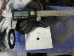
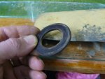
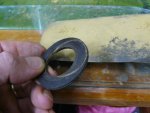
SKF Speedi-Sleeve

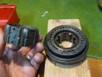
I bet there fun to press on without damage!.... Actually, I'm going to google that ....


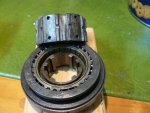
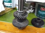
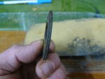
Gee's how easy is that ... He even started with the sleeve sitting on there on a strong angle and just starts hammering :eek: And it didn't destory it!

seeya,
Shane L.
 
Finally I've done a little tinkering.

attachment.php


I'm really hopeless with one of these things ... but we'll get there :)

attachment.php


I turned one of the bushes slightly shorter as you can see (to cater for the offset oil feed hole in the gear). The spacer should work ok, but is far from pretty!

attachment.php


attachment.php


It should work fine though.
 

Attachments

  • P1180872.JPG
    P1180872.JPG
    72 KB · Views: 694
  • P1180870.JPG
    P1180870.JPG
    79.2 KB · Views: 728
  • P1180869.JPG
    P1180869.JPG
    74.2 KB · Views: 683
  • P1180868.JPG
    P1180868.JPG
    67.6 KB · Views: 693
I wasn't going to bother to pull these apart as I reckoned they felt great ....

attachment.php


Gerry was sure they would need to come apart. That's his modified center used to install and extract the spring loaded bearings.

attachment.php


See the bits of metal crap/buildup on the center where I"ve pushed it in out of of the gear a few times.

attachment.php


The reason I slid it in and out a few times was because I couldn't see how to extract the balls (even though gerry did show me about 10times). Like everything it's obvious once it's apart. I just put it in a ziplock bag and pushed the center out.

attachment.php


Look at the buildup of metal and crap in there !

seeya,
Shane L.
 

Attachments

  • P1180760.JPG
    P1180760.JPG
    75.8 KB · Views: 643
  • P1180759.JPG
    P1180759.JPG
    81.4 KB · Views: 668
  • P1180757.JPG
    P1180757.JPG
    75.6 KB · Views: 655
  • P1180756.JPG
    P1180756.JPG
    79.3 KB · Views: 687
moving along ...

attachment.php


I assembled the lower shaft ... and there seem to be a hell of a lot of slop in the bottom gear ( assembly instructions say .05 -> 0.2 is permissable). I measure 0.7 with the new C washer in there (which lock it in 100% tight with no rocking).

attachment.php


So I turned it over and measured between the celeron washer and bearing ... yep, 0.7mm is nice and tight on the feeler gauges.

attachment.php


the celeron washer in there is ~ 2.5mm .... all of Gerrys spares are a maximum of 2.5mm. Now we should be aiming for a 3.0 -> 3.15 mm celeron washer.

I'm guessing it's ok to sand two washers down to 1.55mm and use two in the place of one :confused:

seeya,
Shane L.
 

Attachments

  • P1180875.JPG
    P1180875.JPG
    68.2 KB · Views: 718
  • P1180874.JPG
    P1180874.JPG
    73.2 KB · Views: 870
  • P1180873.JPG
    P1180873.JPG
    82.5 KB · Views: 680
moving along ...

I'm guessing it's ok to sand two washers down to 1.55mm and use two in the place of one :confused:

seeya,
Shane L.

Yes I have done that before. Select two that together are slightly over size Glue them together with Cyanoacrylate and then lap them down to the required 3.5mm using a sheet of glass oil and wet and dry paper 240 should be ok! The sheet of glass gives you a good chance that the washer will remain true in thickness as you sand. Turning the washer through 90 degrees every so often as you go helps to prevent the sanding from taking too much off one side!
The other approach to reducing the longitudinal play of this gear is to insert a steel shim between the thrust race and the gear face. This approach moves the gear back on the shaft. The previous approach moves it forward.
 
Last edited:
Yes I have done that before. Select two that together are slightly over size Glue them together with Cyanoacrylate and then lap them down to the required 3.5mm using a sheet of glass oil and wet and dry paper 240 should be ok! The sheet of glass gives you a good chance that the washer will remain true in thickness as you sand. Turning the washer through 90 degrees every so often as you go helps to prevent the sanding from taking too much off one side!
The other approach to reducing the longitudinal play of this gear is to insert a steel shim between the thrust race and the gear face. This approach moves the gear back on the shaft. The previous approach moves it forward.

I'd face the bush in the lathe every time. Guaranteed parallel (to the limit of the lathe "true").
 
I'd face the bush in the lathe every time. Guaranteed parallel (to the limit of the lathe "true").
Hi Rob these are spacers and also act as thrusts. They are made of resin impregnated cloth. It was supplied under the name of 'Celleron'. I think that they might be very hard to mount in a lathe. I did not have access to one in any case and this was the technique that I came up with. It works very well. It would also be possible to turn up a phosphor/bronze replacement.
 
Hi Rob these are spacers and also act as thrusts. They are made of resin impregnated cloth. It was supplied under the name of 'Celleron'. I think that they might be very hard to mount in a lathe. I did not have access to one in any case and this was the technique that I came up with. It works very well. It would also be possible to turn up a phosphor/bronze replacement.

Sorry Gerry, missed the fact they were celleron washers.

I was still in phosphor bronze "mindset" .
 
Sorry Gerry, missed the fact they were celleron washers.

I was still in phosphor bronze "mindset" .

Yes, you could never machine that as is. They are far to fragile. As it was, the oil spacer above... I crushed the first one I made in the lathes vice... 2nd time around I made it on the bush, then cut it off when it was finished (so the lathe was holding the full sized bush, rather than the frail turned down oil feed spacer).

I think I'll sand down two washers to 1.55mm ..... Then glue them together from the faces that have been sanded (that way it should be nicely keyed). I'm figuring any slight out of roundness will be quickly worn away by the hardened gears it runs against.

seeya,
Shane L.
 
I think I'll sand down two washers to 1.55mm ..... Then glue them together from the faces that have been sanded (that way it should be nicely keyed). I'm figuring any slight out of roundness will be quickly worn away by the hardened gears it runs against.

seeya,
Shane L.
Choose the washers that already come as close as possible to the desired total thickness when placed together. Then there will not be so much to sand down, thereby minimising any chance of error.
BTW Celeron when running in oil against a hardened steel is mighty resilient stuff. I would not count too much on the bedding down process to correct any errors!
 
Thanks Gerry,

once again you are right. Interestingly all of the washers vary in thickness by atleast 0.1mm if you run the calipers around them! They stay the same difference in thickness with sanding.

attachment.php


Very easy to sand down as you suggest. It appears to make no difference to how exact there shape is.

attachment.php


attachment.php


They are a nifty design with the oil feed embossed into one side.

attachment.php


As you suggested, superglue easily glues them together ... I only stuck a couple of fingers to them in the process.

attachment.php


It shows 0.05mm instead of 0.7mm now .... However I know the washer varies in thickness between 3.05 and 3.15 ... So it's within spec ... sort of. Well it's as good as it ever would have been anyway!

I'm pretty sure the process that embossed the oil way, also narrowed the washer by about 0.1mm in that area.

seeya,
Shane L.
 

Attachments

  • P1180882.JPG
    P1180882.JPG
    89.9 KB · Views: 558
  • P1180881.JPG
    P1180881.JPG
    65.4 KB · Views: 637
  • P1180879.JPG
    P1180879.JPG
    60.9 KB · Views: 621
  • P1180878.JPG
    P1180878.JPG
    46.1 KB · Views: 607
  • P1180876.JPG
    P1180876.JPG
    84 KB · Views: 644
Now comes the real fun part, setting up the shim stack to get the correct conical depth for the pinion. Remember that shim stacks (especially when using recycled shims are compressible. This means that it is no use taking a measurement between the 55mm radius of the diff and the pinion face unless the pinion nut is at full torque and that the front bearing cap is fully tightened. Do not use paper gaskets (ever, they are a source of variation) or sealant (only on final assembly) at this stage because it will all have to come apart quite a few times as you alter the shim stack. You will need to include the forward gears and speedo worm on the pinion shaft, and as it is odds on that you will not have the stop tool to immobilise the shaft and gears, a good substitute can be improvised from a socket resting against third gear and the casing with a large screw driver against the socket and the blade held firmly between the teeth of third. The casing will need to be mounted firmly in the vise, otherwise you will run out of hands to hold the screw driver whilst tightening the pinion nut!
The diff assembly needs to be fitted and torqued in so that the Timkens are a little tight but the crown wheel can JUST be rotated! You need to eliminate all sources of variation. This is why the assembly must be stiffer than normal running conditions.
 
Last edited:
Now comes the real fun part, setting up the shim stack to get the correct conical depth for the pinion. Remember that shim stacks (especially when using recycled shims are compressible. This means that it is no use taking a measurement between the 55mm radius of the diff and the pinion face unless the pinion nut is at full torque and that the front bearing cap is fully tightened. Do not use paper gaskets (ever, they are a source of variation) or sealant (only on final assembly) at this stage because it will all have to come apart quite a few times as you alter the shim stack. You will need to include the forward gears and speedo worm on the pinion shaft, and as it is odds on that you will not have the stop tool to immobilise the shaft and gears, a good substitute can be improvised from a socket resting against third gear and the casing with a large screw driver against the socket and the blade held firmly between the teeth of third. The casing will need to be mounted firmly in the vise, otherwise you will run out of hands to hold the screw driver whilst tightening the pinion nut!
The diff assembly needs to be fitted and torqued in so that the Timkens are a little tight but the crown wheel can JUST be rotated! You need to eliminate all sources of variation. This is why the assembly must be stiffer than normal running conditions.

Oh .. thanks. That should be fun trying to torque up the nut on a gearbox sitting on the bench!

seeya
Shane L.
 
Does the gearbox fit in your vise?
If it does not then your are welcome to bring it down here and use my vise. I know that I can get it into mine!

Actually ... I know an easy way ... slip it back onto the engine! with no primary shaft in there it'll just slot on! I should be able to chase a big enough vice locally :)

seeya,
Shane L.
 
That would make things really complicated! I cannot imagine the difficulty in achieving the required precision working whilst hanging into the engine bay. Just not good enough.
 
That would make things really complicated! I cannot imagine the difficulty in achieving the required precision working whilst hanging into the engine bay. Just not good enough.

Oh, I meant, just slide it on to tighten the nut on the front! You wouldn't need to bolt it down :)
 
Top