Another 205 8v thread

That system, used on the Si and the 2 litre 405 SRI is the best ever, never had the slightest problem.
 
Thank you, Alex. Is that similar to Megajolt? I have one of these systems ready to go. The Megajolt runs through a Ford EDIS and fires one coil only (for all plugs).
 
Flock FYI, attached is the XU10J4 ignition wiring diagram. It has two dual channel ignitors, 1105A and 1105B. As fitted to 2L Mi16 and S16. Maybe you could source one of those? However, given you get new pins and boot with the Haltech ignitor, it's probably the better option.

When I enable O2 control on the PS1000, I can't see an option for CAN, only the analogue input.
 

Attachments

  • XU10J4 coils ecu ignitors.jpg
    XU10J4 coils ecu ignitors.jpg
    176.2 KB · Views: 124
I've been doing everything in drips and drabs for the last 10 months. Haven't progressed as well I thought but there is progress, given my hobby-time is between the hours of 930pm and midnight. So to summarise thus far:

ECU Location
I test-fit the PS1000 in a 306 battery box but I was not impressed with the lack of room for fuses/relays and that fact that it ate into that valuable space behind the battery.

IMG_7200.JPG


So I ended up using the plastic base of the Jetronic ECU to mount it in its factory position. After a bit of cutting it fits perfectly. There's room to give some service loop for all the splices. It is not pictured, but I am also mounting the AEM inline wideband in the Jetronic connector slot.

IMG_7457.JPG


The old ECU was an absolute pain the ass to remove. I had to loosen the entire top dashboard to pull out the old loom. Might be a good excuse to put my good dash in...

Fuses and Relays

Rather than use a relay for every circuit like Haltech recommend I ended up going with just 2 relays - EFI and Fuel. The EFI relay is powered up via the ignition switch and supplies the ECU, injectors, wideband and auxiliaries. The fuel relay supples the fuel pump and ignition coil. It's coil negative is switched by the ECU for safety, and coil positive is switched through the EFI relay to provide some reverse polarity protection. One of the fuses also just supplies the positive to the starter relay. The fuse box will mount where the old ignition coil was

IMG_7639.JPG


The loom

I had grand delusions of using milspec wire, concentrically twisted and dr25 - all that overkill wiring-porn. Turns out it is insanely expensive in Australia if you are ordering small quantities. So I went with TXL and high temp braided sleeve. The cores will get dirty but its only the branches that are exposed, not the main trunk. Also the branches were twisted to make them nice and flexible. If I was to do it again I'd try to get my hands on techflex insultherm trufit - a resin fibreglass sleeve. Here's a photo I took this morning:

IMG_7915.jpg


In case someone wants to make it sequential in future all the injectors are individually wired, there's a spare cam sensor multicore and 2 spare ignition channels. For this reason, the ignition was made into a sub-harness - which I already regret.

And the little fella has been helping me along the way:

IMG_7436.JPG


Final touches I need to make to the loom are some velcro heat sleeve on the firewall exit and find some male pins for the brown multiplugs in the cabin. If anyone knows where to get these if they still exist please let me know.

The 'upgrades'

Peter gave some sound advise so I did not go too crazy. I gave up on the idea of using the 306 throttle body. The only additions really are the MAP sensor, crank sensor, analog TPS, wideband and wasted spark.

The Weber PF09 is an analogue TPS with the same bolt pattern as the old Bosch switch TPS. Only thing is they have 2 linear curves but I still wanted to give it a go. But at $250 for a genuine part that stopped me in my tracks. I tracked down the aliexpress version for $15. It measured fine (1-2k range) but the resistance was a bit unstable - I thought it was my meter leads. Turns out they tried to solder a steel spring onto copper contacts. So it went in the bin and I moved on to making an adapter plate for the 306 TPS.

IMG_7372.JPG


Instead of wiring up the cold start valve to a hard positive and earth, I have it switched via the ECU. This is so that in future if I want to use a PWM idle valve it's ready to go.

The crank sensor is from my Si gearbox. I originally thought it was just an inductive sensor so I wired up my multicore at the ECU as +/- going straight into the ECU. But I am pretty sure being a 3-pin it is a hall-effect. Lucky I used 3-core. Reading some old posts Peter suggests using a resistor in series to drop the voltage. Not sure if this is still the case. If I can use the 8v supply from the PS1000 I just need to unspare one wire and terminate it.

At this stage the wideband is just going where the old Lambda sensor was. I roughly measured with my phone and it is angled about 10 degrees so it shouldn't have issues.

Things yet to fix

I have always had breather issues since before the engine rebuild and originally I put it down to worn rings and excessive blowby. It has about 1000kms on it now and when I removed the manifold there's a film of oil coating the ports. I am not sure if this is to be expected with a new engine or there is something wrong. The PCV from the rocker cover is always sweating oil since it is silicone.

IMG_7599.jpg


I also found coolant under the head studs at the front and I thought I might have cracked the block. But turns out there's tiny holes for coolant that the manifold gasket is meant to contain. The gasket I was supplied doesn't appear to be doing its job so a bit of threebond might be needed there.

The thermostat housing from the Si head (to delete the dizzy) is missing this press-fit bleeder valve. So I either have to find another or machine up a blanking plate for the distributor.

IMG_7765.jpg


I have also just learnt that Chilton Engineering at Woollongabba has closed up shop.

So that's it. More to come soon.
 
Nice update, good work!!

Sad to hear that David has closed up shop. I'll have to find a new place!!
 
The crank sensor is from my Si gearbox. I originally thought it was just an inductive sensor so I wired up my multicore at the ECU as +/- going straight into the ECU. But I am pretty sure being a 3-pin it is a hall-effect. Lucky I used 3-core. Reading some old posts Peter suggests using a resistor in series to drop the voltage. Not sure if this is still the case. If I can use the 8v supply from the PS1000 I just need to unspare one wire and terminate it.
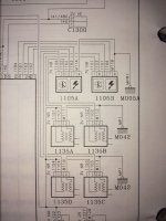
I think you'll find it's an inductive sensor, as per attached, even though it's 3 core. The 3rd wire being the shield. Great progress, keep us posted.
 

Attachments

  • SENCSA5.pdf
    102.9 KB · Views: 94
Thanks for sharing that doco Peter, it is indeed a reluctor in the end. I hooked up 12V to the ECU and auxiliaries last night and can confirm all the sensors are behaving as expected, just need some calibration. Only thing is the AFM AIT, there is no data on it so I need to do manual cal. If I can confirm my spare AFM has the same resistance when ambient I'll dunk the sensor in a pot of water.

I made an attempt at gutting the spare AFM. The baseplate under the spindle is sealed shut and won't budge even with all the little rivets chiselled off. I'll leave it for now. My preferred solution still, is to find somewhere on the throttle body to bung an AIT in and delete the AFM completely.

Currently using ECU manager in a Win10 VM on the wife's 10 year old Macbook air. Still has the best battery of all laptops in the house, apart from her new MBA.
 
Wish I was home and I would come over to gawk at this, nice work. In Vic going to SA. I have a good engineering shop but not an engine specific shop.
 
More updates and piccies:

TPS adapter done, just need to make it pretty.
IMG_8002.jpeg


Haltech in it’s finally location:
IMG_8163.jpeg


I tried the relay tacho mod. Gutted the mech and hooked up 12V to one side of the coil, with the tacho and ecu output in parallel on the other side. I can’t seem to get any deflection in the needle. At first I was just passing a strong magnet past the sensor and seeing what came out. I measured from the tacho input on the dash:

IMG_8231.jpeg


The sampling rate of this little handheld is pretty poor. I didn’t expect much from an advertised 40Mhz BW but even going down as far as 1us it couldn’t pickup the back-EMF. So our came the trusty Tek:
IMG_8241.jpeg


I was getting between 40-60V spikes so one would think that is adequate enough. Nothing like the 400V peaks I measured on the original coil, but at the same sampling rate I still measured 40-70V on the old coil:

IMG_0728_Original.jpeg
IMG_0726_Original.jpeg


Anyway I thought that was good enough to send it. I temporarily changed the setting in the ecu to think it was a 4-1 trigger and attached my E-bike’s magnetic trigger wheel to a drill:

IMG_8244.jpeg


This gave a really decently high Hz to the tacho but still, no deflection (ignore the measured amplitude I didn’t set the compensation in the scope).

IMG_8245.jpeg


I can confirm the 3 wires to the tacho are 12v (parallel with the STOP light), earth and the input. I set the output of the Haltech to 50% Duty @ 4 cycles per rev.
 
The relay tacho mod didn't work, with various coils when connected to the PS1000. I suspect the output protection was clamping the voltage spike. So I bought a tacho driver and it worked straight up.

Instead of gutting the AFM, I bought some 70mm aly tube, cut to length and chamfered on a linisher - cheaper than swaging. The throttle body side hose slipped on fine, but the air filter side needed some hot water to stretch it out a bit.

Finally looking like an engine bay again. If I had a smaller battery I could have mounted the PS reservoir in its factory location, but deleting the AFM made buckets of space to jam it between the battery.
IMG_9801_resize.jpg


If anyone is interested I have found various electrical bits that can be sourced from China. The grey connector from the shunt box to jetronic loom was something I wanted to do properly. Problem is, TE need large quantity orders. I can confirm what I got from Aliexpress is of sufficient quality to trust it will perform.

The TE number for the modern equivalent of the grey connector is 1544458-2. China's number is DJ7027Y-7.8-21 and some vendors include the terminals.
1700789382002.png
IMG_9800_resize.jpg


I also bought some male terminals to rewire the brown multiplugs under the dash. TE: 144838-2 or China: DJ617-4.8X0.8B. I am yet to test fit them as the tabs look slightly different but if it works it certainly beats soldering / blob of deutsch connectors.

Thanks to run205 I also deleted the original coolant sensor block and found the SI bolt holes can still hold the SAD by itself. Might be getting a 405 idle valve off Matt (when I replace his 4B7700H rod bearings I urgently stole for the rebuild).

I still need to install the AIT sensor now that I deleted the AFM. I bought a fast reacting Bosch 0280130085 (mostly because it had a datasheet) but I need to weld a boss to the intake tube - the standard screw in type is what they use in the SI and would have probably sufficed and be easier to weld a bung on (but no datasheet).

Also need to find somewhere to mount the remote MAP and find a suitable tee. For now I'm using a 4mm irrigation fitting but its not ideal. I really want to see if an M8-4mm nipple will work in place of the screw where the catch can is.
 
Excellent work and great info. Why did you want a remote MAP sensor, rather than using the internal of the PS1000?
 
Thief, at least an intelligent / thinking one. We all want a remote MAP sensor don't we?
 
We all want a remote MAP sensor don't we?
I've always thought the internal MAP sensor has the same resolution and range as an external sensor. Certainly for an NA application. I'd rather use more 4mm hose than run another three wires.
 
It certainly would / should but I prefer wiring as does he, just the way we are going!

It was tongue in cheek and not meant to upset, offend or anything else.
 
Finally looking like an engine bay again. If I had a smaller battery I could have mounted the PS reservoir in its factory location, but deleting the AFM made buckets of space to jam it between the battery.
That does look very neat.
A bit late to the party for ideas, but PS reservoir from a 306 might just fit in front of drivers side strut tower and still clear the A/C receiver/drier.
Another thought is the 306 windscreen washer tank is located below inner guard and needing room only for the 60mm tube to fill it.


I've always thought the internal MAP sensor has the same resolution and range as an external sensor. Certainly for an NA application. I'd rather use more 4mm hose than run another three wires.
I'd always go for the three wires and a shorter vacuum hose (with an appropriate restrictor 'pill') so the MAP signal reacts quicker than it does at the end of a long hose.
 
Peter, you always bring that up! When making the new loom I figured why not run 3 extra wires and just have a clean cable entry through the firewall. There is a spare gland though if I so desired to poke a hose through.

It’s a 1.15bar sensor so technically has more sensitivity than 3bar once it’s converted to digital (0.01psi vs 0.04psi on a standard 10-bit ADC). It’s splitting hairs though for even a 32x32 table and not worth arguing over. This particular one had a jetronic connector.

A T-MAP sensor welded onto the manifold in the centre would be the ultimate to get both AIT and MAP. But these manifolds get oily and the datasheet mounting angle puts it at odds with the internal castings.

I made some rough measurements of a 306 PS reservoir and thought it wouldn’t fit. But I would love to be proven wrong!
 
Top