The plastic 306 AIT sensor from the 306 throttle body fits snugly in the same hole as the EVAP purge control line. Quick way to get up and running…


You are using an out of date browser. It may not display this or other websites correctly.
You should upgrade or use an alternative browser.
You should upgrade or use an alternative browser.
Another 205 8v thread
- Thread starter flock
- Start date
This was the state of my ignition barrel harness. No heatshrink just electrical tape. My spare from the other car was more or less the same.

So I made another one using bits from both. The hardest part is getting the boomerang back on without the spring flying across the room. I used some grease to hold the spring and boomerang in place then squeeze the assembly together.

At this point I tested priming the fuel rail, cranking and generally just checking nothing would go bang. When I was satisfied I pulled the fuel pump fuse and put in the ignition fuse to see if I was getting spark.
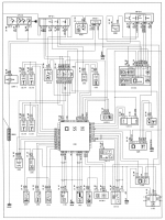
I got the missus to crank the car while I was using the timing light. I was only getting spark on one bank. For reference here is the diagram for the wasted spark coil someone posted on drivers forum. Pins 3 and 4 are the same, with one meant for a capacitor. Luckily the way the pins are orientated it doesn't let smoke out if you wire it ass-about like I did initially.

Another mistake I made was thinking I was safe just pulling the fuel-pump fuse. I didn't think the injectors would still fire. Of course they did, and the car tried to start with the residual fuel pressure. Missus complained she smelt smelt fuel which did not sound good (I can't smell). It was a blessing in disguise as I found I had forgotten to tighten the bolts for the manifold.
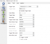
Now that both banks were firing it was time to confirm timing. Initially I set the trigger angle at 72 degrees thinking this is 12 teeth after TDC according to PeterT's article. However I wasn't getting a sync on the TDC mark locking the ignition to 0deg.
Matthew stopped by on his way through and corrected my mistake. He recalled a value of 114 degrees but we could not confirm where. So we put in a 7 tooth offset (6degx7=42+73=114). And sure enough it was pretty well bang on.
We got the car started and idling very roughly and rich with the basic haltech VE base map. But it does start!
So I made another one using bits from both. The hardest part is getting the boomerang back on without the spring flying across the room. I used some grease to hold the spring and boomerang in place then squeeze the assembly together.
At this point I tested priming the fuel rail, cranking and generally just checking nothing would go bang. When I was satisfied I pulled the fuel pump fuse and put in the ignition fuse to see if I was getting spark.
I got the missus to crank the car while I was using the timing light. I was only getting spark on one bank. For reference here is the diagram for the wasted spark coil someone posted on drivers forum. Pins 3 and 4 are the same, with one meant for a capacitor. Luckily the way the pins are orientated it doesn't let smoke out if you wire it ass-about like I did initially.
Another mistake I made was thinking I was safe just pulling the fuel-pump fuse. I didn't think the injectors would still fire. Of course they did, and the car tried to start with the residual fuel pressure. Missus complained she smelt smelt fuel which did not sound good (I can't smell). It was a blessing in disguise as I found I had forgotten to tighten the bolts for the manifold.
Now that both banks were firing it was time to confirm timing. Initially I set the trigger angle at 72 degrees thinking this is 12 teeth after TDC according to PeterT's article. However I wasn't getting a sync on the TDC mark locking the ignition to 0deg.
Matthew stopped by on his way through and corrected my mistake. He recalled a value of 114 degrees but we could not confirm where. So we put in a 7 tooth offset (6degx7=42+73=114). And sure enough it was pretty well bang on.
We got the car started and idling very roughly and rich with the basic haltech VE base map. But it does start!
Attachments

114º is the raw angle. It takes a long time to get from 114º to say 39º (ie 30 base + 9 of light load advance). If your ecu is smart enough, you can add a trigger offset, to make that initial point occur earlier. You can also have a variable trigger, which takes account of variations in the base trigger point due to RPM fluctuations of the trigger. This can be up to 2º. I'll post some screen shots later.
If you read Peter's article it states the tdc marker you bolt on to the block is 72 degrees but the CAS is another 7 tooth further, all up 114 degrees. Now to sort out the fuelling advance as mentioned it should make a big difference. I am very glad you made this mistake and I got to understand this as my Speeduino will be next level. You have your work cut out now sorting VE and then closed loop AFR
That'd be fantastic, thank you.Would you like me to email you a map? It will be for an XU10J4. You'll just have to change it to multipoint, etc. but all the setup and correction maps will be set.
I've already found a lot of things I needed to change like injector flow, dead time etc. The mob who cleaned my injectors tested the dead time at 13.8V so I have extrapolated an approximate curve using data from similar Bosch injectors. The idea is to get a safe and stable map to drive to a tuner.
The datalogging is quite useful to see how hilariously bad it idled. Here's a log from the first start with some throttle blip.
Alrighty, next milestone complete.
Disclaimer: This is totally new to me. Peter has been feeding me pointers in the background for which I am very grateful, given I only get a chance to fire up the car once a fortnight or so.
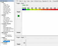
So when I originally loaded in Peter's mi16 map it was far too rich at idle. He recommended I try a zero-throttle map to figure it out. The injection time was far too high to begin with so I managed to get it idling when hot with static times of ~3ms. Of course this meant I had to hold the accelerator ever so slightly to get it to warm up on the enrichment map. This is where I realised it was idling on the far right side of the map. With ECU manager, there is a moving cursor on the Y-axis and a cursor on the table itself. It was idling at 0kpa, which unbeknownst to me was totally wrong but I adjusted the VEs anyway to get a steady idle. I wondered why my VEs were so low in the 20s but I thought it was maybe a result of the cams.

It wasn't until I started loading up the engine trying to pull it out of the garage that I realised the pointer wasn't moving along the load x-axis at all. So I pulled up the load-kpa fuel gauge and clicked to me that it was a 1-1 relationship with MAP. And of course, being +57 kpa the pointer was actually off the chart but bound to the 0.0kpa column.
It turns out I calibrated my MAP sensor how megasquirt guys would, with 0kpa as full vacuum and 100kpa as atmospheric (absolute). Peter's map, following standard practice of Haltech load mapping whereby 0kpa is atmospheric and -100kpa is full vacuum. Makes sense given the legacy of using vacuum/boost gauges. This also affects how the ECU calculates its air mass.
I expected it to idle in the -50kpa range so I set all my values at the low 20s to begin with. It died straight away. I put in sensible VEs close to Peters map and it fired up straight away to a steady cold idle and happily set there up to temperature after some adjustments to get close to the target idle AFR. Forgive the blurred image, it would be rude to blatently share Peter's IP.

Reluctant to take it for a drive yet without a wingman and see how well Quicktune works. Looking at you Matthew
My latest problem is after putting in a new coolant reserviour I realised the sensor was never properly connected so it's now showing as low coolant. I pulled out the reed switch and found a pinhole in the silicone stuff they encased it in. Subsequently the conductor was broken and the reed switch doesn't actuate in the presence of any magnet. I'll see what I can get from Jaycar and make a new one.


Disclaimer: This is totally new to me. Peter has been feeding me pointers in the background for which I am very grateful, given I only get a chance to fire up the car once a fortnight or so.
So when I originally loaded in Peter's mi16 map it was far too rich at idle. He recommended I try a zero-throttle map to figure it out. The injection time was far too high to begin with so I managed to get it idling when hot with static times of ~3ms. Of course this meant I had to hold the accelerator ever so slightly to get it to warm up on the enrichment map. This is where I realised it was idling on the far right side of the map. With ECU manager, there is a moving cursor on the Y-axis and a cursor on the table itself. It was idling at 0kpa, which unbeknownst to me was totally wrong but I adjusted the VEs anyway to get a steady idle. I wondered why my VEs were so low in the 20s but I thought it was maybe a result of the cams.
It wasn't until I started loading up the engine trying to pull it out of the garage that I realised the pointer wasn't moving along the load x-axis at all. So I pulled up the load-kpa fuel gauge and clicked to me that it was a 1-1 relationship with MAP. And of course, being +57 kpa the pointer was actually off the chart but bound to the 0.0kpa column.
It turns out I calibrated my MAP sensor how megasquirt guys would, with 0kpa as full vacuum and 100kpa as atmospheric (absolute). Peter's map, following standard practice of Haltech load mapping whereby 0kpa is atmospheric and -100kpa is full vacuum. Makes sense given the legacy of using vacuum/boost gauges. This also affects how the ECU calculates its air mass.
I expected it to idle in the -50kpa range so I set all my values at the low 20s to begin with. It died straight away. I put in sensible VEs close to Peters map and it fired up straight away to a steady cold idle and happily set there up to temperature after some adjustments to get close to the target idle AFR. Forgive the blurred image, it would be rude to blatently share Peter's IP.
Reluctant to take it for a drive yet without a wingman and see how well Quicktune works. Looking at you Matthew
My latest problem is after putting in a new coolant reserviour I realised the sensor was never properly connected so it's now showing as low coolant. I pulled out the reed switch and found a pinhole in the silicone stuff they encased it in. Subsequently the conductor was broken and the reed switch doesn't actuate in the presence of any magnet. I'll see what I can get from Jaycar and make a new one.
Last edited:
Definitely up for it as I have so much to learn as you well know! And just so you know I hate analogue crap, analogue computers (controlled early rockets), telemetry and especially control systems, magdick did me a Favour there. So much to learn and its been a good journey.
I just had the same problem with my coolant level sender
is yours located in the reservoir ? or the top front right of the radiator ?
got lazy and just bought a new one from the Peugeot shop
but your fix is the better way
is yours located in the reservoir ? or the top front right of the radiator ?
got lazy and just bought a new one from the Peugeot shop
but your fix is the better way
Well done! And thanks for thinking about IP. I’m obviously happy to share a map with anyone who asks nicely.
The trick to Quicktune, is keeping the load in the centre of a cell, so it’s not interpolating. Then hit Q. Hitting Q followed by W, will do cell above and to the right. It gets difficult to do 5000 rpm in 5th at 0kPa
The trick to Quicktune, is keeping the load in the centre of a cell, so it’s not interpolating. Then hit Q. Hitting Q followed by W, will do cell above and to the right. It gets difficult to do 5000 rpm in 5th at 0kPa
Peter,Belzona is a much better product than Devcon or JB Weld.
Belzona, where do you find it?
I'd ring Rezitech and find out who your closest reseller is.Peter,
Belzona, where do you find it?
Also look at Splash Zone.Peter,
Belzona, where do you find it?
Coolant reservoir.I just had the same problem with my coolant level sender
is yours located in the reservoir ? or the top front right of the radiator ?
got lazy and just bought a new one from the Peugeot shop
but your fix is the better way
Well done! And thanks for thinking about IP. I’m obviously happy to share a map with anyone who asks nicely.
The trick to Quicktune, is keeping the load in the centre of a cell, so it’s not interpolating. Then hit Q. Hitting Q followed by W, will do cell above and to the right. It gets difficult to do 5000 rpm in 5th at 0kPa
Matt and I had a play yesterday in my driveway. Felt like some black magic trying to hold revs and hitting Q at the centre point with the cursor flickering about. After he went home I fired up the datalogger and realised I hadn't turned off O2 control, which was problably fighting us.
Alrighty, next milestone complete.
Disclaimer: This is totally new to me. Peter has been feeding me pointers in the background for which I am very grateful, given I only get a chance to fire up the car once a fortnight or so.
So when I originally loaded in Peter's mi16 map it was far too rich at idle. He recommended I try a zero-throttle map to figure it out. The injection time was far too high to begin with so I managed to get it idling when hot with static times of ~3ms. Of course this meant I had to hold the accelerator ever so slightly to get it to warm up on the enrichment map. This is where I realised it was idling on the far right side of the map. With ECU manager, there is a moving cursor on the Y-axis and a cursor on the table itself. It was idling at 0kpa, which unbeknownst to me was totally wrong but I adjusted the VEs anyway to get a steady idle. I wondered why my VEs were so low in the 20s but I thought it was maybe a result of the cams.
View attachment 235580
It wasn't until I started loading up the engine trying to pull it out of the garage that I realised the pointer wasn't moving along the load x-axis at all. So I pulled up the load-kpa fuel gauge and clicked to me that it was a 1-1 relationship with MAP. And of course, being +57 kpa the pointer was actually off the chart but bound to the 0.0kpa column.
It turns out I calibrated my MAP sensor how megasquirt guys would, with 0kpa as full vacuum and 100kpa as atmospheric (absolute). Peter's map, following standard practice of Haltech load mapping whereby 0kpa is atmospheric and -100kpa is full vacuum. Makes sense given the legacy of using vacuum/boost gauges. This also affects how the ECU calculates its air mass.
I expected it to idle in the -50kpa range so I set all my values at the low 20s to begin with. It died straight away. I put in sensible VEs close to Peters map and it fired up straight away to a steady cold idle and happily set there up to temperature after some adjustments to get close to the target idle AFR. Forgive the blurred image, it would be rude to blatently share Peter's IP.
View attachment 235581
Reluctant to take it for a drive yet without a wingman and see how well Quicktune works. Looking at you Matthew
My latest problem is after putting in a new coolant reserviour I realised the sensor was never properly connected so it's now showing as low coolant. I pulled out the reed switch and found a pinhole in the silicone stuff they encased it in. Subsequently the conductor was broken and the reed switch doesn't actuate in the presence of any magnet. I'll see what I can get from Jaycar and make a new one.
View attachment 235582 View attachment 235583
If you can solder back the wire, I would do that. No other reason but lazyness. Jaycar/Altronics do have reed switches that fit.
I have used one of their switches but I also replaced the glassfibre stem with a brass tube from a hobby shop. You can get all sorts of sizes, I chose one with thin wall that slides very nicely inside the ring magnet. Capped the bottom with some scrap brass and soft soldered it and turned a fitting for the top on the lathe to make it a fest fit over the o-ring at the top, soldered that at the top of the tube. I expect it will outlast the car. If you don't have a lathe you can choose a tube size close to the size of an old brass wheel valve cap and solder that at the bottom. For the top you can buy a large enough brass tube (at the hobby/model shop) and make a disc of brass from sheet (or use a suitable brass washer) to create the top and solder it to the tube.
Correct. Do you want me to have a look at the O2 table?Matt and I had a play yesterday in my driveway. Felt like some black magic trying to hold revs and hitting Q at the centre point with the cursor flickering about. After he went home I fired up the datalogger and realised I hadn't turned off O2 control, which was problably fighting us.
Thanks for that updated table Peter I took it for its first drive yesterday. AFRs all over the place, mostly lean though but at least there was no pinging. I was able to drive at a steady 2500rpm and Q in some values. But to achieve target AFR this means the VE numbers at the selected rpm are really high at 85%. Relatively speaking this shouldn't matter if tuning the whole table from scratch, but something is still odd.
I found another detail I have missed.
Looking back at my earlier posts I only have a 2.5bar fuel regulator (0 280 160 227). My injectors (0 280 150 734) were flowed at 236cc/min @ 3bar and the base fuel pressure setting in the Haltech is also at 310kpa. So I guess that means the ECU is expecting a higher fuel delivery.
In the short term I'll throw in a calculated value of 215cc/min and 250kpa base pressure and see how it behaves. I expect the VEs to be at least 10% lower.