My new challenge - 1964 ID19F Safari

The medium of using pastels in the art world has a disadvantage in that. unlike oils or watercolour it doesn't "dry".
A spray of sealer after the work is finished prevents the pastel from scuffing when handled.
After you left today with the good speedo glass, I've been playing with the idea of spraying the reverse of the glass with a laquer to prevent the deterioration or the the numbers.
A risky business .......... probably ! The spray might discolour or disfigure the numbers even more.
Any thoughts on this ...................... Michael Paas
The problem with a lacquer is if it is too "hot", you could easily destroy the decal used to mark the speedo. What might be a better option would be have a transfer decal made from the original glass, remembering that you need to make it in reverse! UV protection would also be good.
You might be able to lay a clear mask over the original- the stuff used to make a clear "bra" for exterior paint. That stuff is pretty thick though, so I don't know if there is enough room between the glass and the speedo needle.

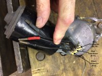
Sven, I think I've located a proper VR for your car. I'm going to talk to the owner (he has several, supposedly) and see if I can get him to send me a couple.
 
I wonder if you could make up a silkscreen and reprint the lettering onto the glass. It shouldn't be to hard to make the artwork from the good speedo glass you have
 
I wonder if you could make up a silkscreen and reprint the lettering onto the glass. It shouldn't be to hard to make the artwork from the good speedo glass you have

One for greenblood?
 
Spent the weekend installing Bill’s wiring loom - threading the rear loom through those tiny 20mm holes and through the sill is one of those painful exercises... one wonders how they did this in the factory at speed...

but: once I had that part worked out, the loom fit super well - and with the labelling in place it was easy to reconnect it all. I think I even worked out how to install the door switch upgrade for the interior lights. The car didn’t have those originally.

8C0E1A97-3B80-4B91-8015-E68EC05A829C.jpeg
D88827FD-2F31-4DD6-B81E-4867A1C8B7A3.jpeg
01F3E894-4DC7-4736-9C4D-3CDA0A83EF74.jpeg
ADE2150E-F9EF-4B12-8B28-96BC61CEF9BC.jpeg


To add a splash of colour, I painted the blue and yellow rings onto the spheres - using my wife’s pottery wheel 😬. That worked extremely well...

DB753973-3AE8-46D6-BDC2-C05140FAA9CE.jpeg


207264FF-62D2-47DF-A322-4220CD26D042.jpeg


Next on the to do list was the roof rack. After stapling the rubber gaskets together and twirling the leading edge rubbers onto the front bar, the whole rack went together well and looks fantastic. It will be carrying an old leather suitcase for sure... maybe even a surfboard!

0E3DBC0E-C925-420E-8555-23F5E66E8B93.jpeg
6C95A82F-E88B-4369-A5DA-624455E29EF8.jpeg


One item on the wiring however has me stumped a little: the windscreen wiper motor I have has three wires coming out, but the diagram only shows two wires (yellow and black) coming in. Looking at old photos, two of the wires (assuming the two black ones) seemed to have been combined, but is that correct?

What are the three wires? Fast speed, low speed and ground? Is it correct to just combine the two black wires into the one?

8D07EB41-6AF3-49C8-8610-A9B6E1D067D0.jpeg
A58E35E2-347D-435C-A09A-701E09DCC1CE.jpeg


Sven
 
There is a power supply that comes from the switch.
Then there another that is always on when the ignition is on. This is to power the wipers back to their parked position after the switched power goes off.

In the parked position the constant power is interrupted, but the switched power is able to restart the wipers.
 
Hi

I looked into the wiring of a two speed, three wire motor. In my case in was in relation to a 67/68 car - so the wire numbers on the photo won't relate to your age of car. However i hope my note and photos provided enough clues for you to be able to rig something up - if you can get a dash switch with three contacts. Are your knob caps gold? Maybe an Ami switch will fit? Here goes:

1967/8 wiper connections

NOTE:

There are two twisting switches on the dash with an arrow marking. One has four connections. that’s for the parking lights. the other has three connections. that’s the one for the wipers.


SOURCE OF POWER.
There is a wire coming from the starter relay daisy thing connected to the positive terminal of your battery. If it still has the original tag, it will be a yellow tag. This wire is a constant live feed and goes into fuse 2 as ‘J 2’

A yellow tagged wire (J 6) comes off fuse 2. It’s live remember. Hidden within the loom isplits into two branches:

one branch (a live feed) goes to the connection on the wiper switch that has a green paint blob

Another branch (again a live feed) goes to the black connection on the wiper body


Other Connections
Connection on the switch with a red paint blob is connected directly to 'red' on the wiper body

Connection on the switch with a blue paint blob is connected directly to 'blue' on the motor.


Earth
Up to February 1968 the wiper system was simply earth by virtue of being screwed to the chassis. From Feb 68 an earth lead was fitted to one of the wiper body screws (and the other end screwed to the chassis). it won’t hurt to add a flying earth lead if your car is pre-feb 68.
 

Attachments

  • wiper connections copy.jpg
    wiper connections copy.jpg
    534.8 KB · Views: 144
  • wiper switch copy.jpg
    wiper switch copy.jpg
    546.8 KB · Views: 135
  • Wiring on spare wiper motor2 copy.JPG
    Wiring on spare wiper motor2 copy.JPG
    720 KB · Views: 148
Sven, I'm so excited to see the loom go into the car. Been quite a while coming. And it actually fits! YAY!! I was worried the rear would be a problem, and actually made up another rear loom without the trailer hookup just in case.

The loom I copied only had the single-speed wiper. The switch would have been one of those simple pull on/push off ones. N26 as noted on your diagram is a little different from the one I followed. The thing to note here is N8 on my diagram goes to a few different circuits, one of them being a power feed for the accessory tap, one being the constant feed for the wiper motor, and another for the clock (which you don't have). In other words, it does not feed from the tap. but rather from the loom itself. So, you have J11 and N8 for your hookup at the motor. The wiper motor grounds through the motor body to chassis, although you can add a ground strap (motor-to-chassis) if you like.

Your motor appears to be a later 2 speed: low, high, and park- not ground! N8 is the park. J11 would be your low. You can retain the wiper motor, but you'll need to add a wire and a 2-speed switch.

Edit: If you do change over to a two-speed system, you can easily change out the color sleeves too, to reflect the switch markings. Just note it on your diagram.

http://bk23.free.fr/MR/DR472_64_ID19PLANCHES.pdf page 171
http://bk23.free.fr/MR/DR472_64_ID19TEXTE.pdf page 414

May I ask you for a link to your diagram? If yours is that different from mine on just the wiper motor, what else am I going to find?
 
Hi

I looked into the wiring of a two speed, three wire motor. In my case in was in relation to a 67/68 car - so the wire numbers on the photo won't relate to your age of car. However i hope my note and photos provided enough clues for you to be able to rig something up - if you can get a dash switch with three contacts. Are your knob caps gold? Maybe an Ami switch will fit? Here goes:

1967/8 wiper connections

NOTE:

There are two twisting switches on the dash with an arrow marking. One has four connections. that’s for the parking lights. the other has three connections. that’s the one for the wipers.


SOURCE OF POWER.
There is a wire coming from the starter relay daisy thing connected to the positive terminal of your battery. If it still has the original tag, it will be a yellow tag. This wire is a constant live feed and goes into fuse 2 as ‘J 2’

A yellow tagged wire (J 6) comes off fuse 2. It’s live remember. Hidden within the loom isplits into two branches:

one branch (a live feed) goes to the connection on the wiper switch that has a green paint blob

Another branch (again a live feed) goes to the black connection on the wiper body


Other Connections
Connection on the switch with a red paint blob is connected directly to 'red' on the wiper body

Connection on the switch with a blue paint blob is connected directly to 'blue' on the motor.


Earth
Up to February 1968 the wiper system was simply earth by virtue of being screwed to the chassis. From Feb 68 an earth lead was fitted to one of the wiper body screws (and the other end screwed to the chassis). it won’t hurt to add a flying earth lead if your car is pre-feb 68.
Yah- 6 on yours is 8 on mine (Sven's). Keep track of that, changing over to 2-speed is a doddle. Fitting a 2-speed switch shouldn't be a problem- it can't possibly be larger than the park lamps switch.

May I have a copy of the link to your diagram as well, please? Frederic Fortune's page is astonishingly detailed, but not complete.
 
Thanks Budge and Bill for the quick reply and instructions. I will digest it properly tonight.

I wouldn’t be surprised that the motor was changed... even though the attachment plates all fit for the older cars. Anyway, a three way switch may work. Might still have a spare one (yes, mine have the golden inserts).

Otherwise, is there a way to use the three way wiper motor with the current two wire switch? I don’t really need two speeds... will try to not drive in the rain wherever possible 😖

I think the other item that may have been “retrofitted” was the heater fan box on the passenger side... it’s in the -5 version of the diagrams. But it only seems to need one wire, a switch and earth, so shouldn’t be hard to add either.

I also have two b-pillar courtesy lamps, with all the diagrams only showing on on the passengers side, so I will extend the loom from the rear lid light over to the drivers side lamp. Again, a simple job. Might have been another export special for Australia.

might take me a little longer than it would take the professionals, but I will get there... 😬

The loom fits super well Bill. You have done an outstanding job. I can’t thank you enough. The tow bar wiring might come in handy one day...

Sven
Hooking up for a single wire wiper should be nothing: your black-marked lead would be the N8 lead coming off the new loom. You can hook the J11 lead to either the blue or red lead. One will give you high speed, the other low speed. Set the motor how you want, insulate and tuck away the other lead.

Sorry about the driver side courtesy lamp. I did not know about that one, just the passenger side and the rear lamps. Making a "Y" from the rear as you mention would be the easiest.

I meant to tell you: using the new insulators for the 4mm female terminals, a couple of pointers. 1) make sure you apply any color sleeve before you put the insulator on. The .25" shrink tubing I use for color is just a wee bit smaller in diameter than the rubber. Ask me how I know! 2) Dip the rubber into some rubbing alcohol before applying. Acts like a lubricant, dries quickly, leaves no mess, and has the effect of bonding the rubber to the terminal. The only drawbacks are you need to work quickly, and if left to set, you may need to cut the rubber off if you goof up.

For the bulb grease you got, that was primarily for ease of assembling pin-to-socket. It'll also help reduce the possibility of corrosion later on. A little dab to the opening, slip the terminal together, and Robert isn't your aunt (well, in this day and age, who knows anymore??).

For the heater fan, you can actually take power from the Vi9 circuit at the ignition switch.
http://bk23.free.fr/MR/DR472_64_ID19PLANCHES.pdf page 168, figure 2
You can "y" it off just like the driver courtesy lamp.

Oh one last thing, the crimpers you got: those are what we refer to as a single nest style. In other words, you need to make two crimps, one for the wire, one for the insulation. You'll do well to add a drop of solder once the crimp is made. You "can" get two wires into the terminals, but it takes a bit of practice, and nothing more than a pair of 16ga. (the size used through most of the dash and rear harnesses). If the wire isn't stressed or pulled tightly, you can strip the wire enough to use both crimps on bare wire, solder, then use two color sleeves to insulate (one atop the other).

"Professionals"?!!? You take that back!!:mallet::D
 
Now that I got the last of the electroplating back from Lyndale Plating in Dandenong (can recommend them - talk to Andrew, cash is king) I could finish the roof rack and also get on with lining the inside of the roof, ready for the headliner fabric and seal. I ordered four sheets of 6mm foam from Carbuilders (thanks KAndy for the tip) - it went on easily and will provide a good base for the headliner and also covers the screw heads of the roof rack.

FE1D01F3-80BB-4760-9477-7E38E5522962.jpeg
D3671729-D6B6-47CA-8808-8514F55FD7F2.jpeg


With the roof off I was able to finish the wiring to the interior courtesy lamps and extend the wiring to the drivers side B-pillar for the second interior light.

8527FDEE-CC0C-43E5-82F8-D8417C9DD847.jpeg


Gluing on nice new silver sill vinyl with new seals was one of the nicer jobs. The door stays received new plastic rollers and new stainless cover plates.

ED85378E-F808-46F0-AB49-FE192FAAE9C7.jpeg


The air intake ducts were rebuilt and installed with new firewall seals.

A54A84E1-FDEF-496F-8A4D-C9EE90159CB6.jpeg


I hope I got the handles the right way round... can anyone confirm? The knob ends facing away from each other?

27D177B3-1C8D-4231-9A24-E66984E2C4DC.jpeg
4983D91B-5CED-48E1-AAF6-2D500FF94BAA.jpeg


Sven
 
Nice work on those vents. What size aluminium rivers did you use please? And what about those log rods? Did you have to grind the ends off (and - if so - how did you put the shortened rods back?) Or did they have some kind of push-fit cap on the other end? New felt or cleaned?

Questions, questions....
 
Budge, well:

- I used 4mm Aluminium rivets, semi hollow 8mm long - they work really well and are simple to use

- log rods? I assume you mean the horizontal rods that hold the felt flaps? They had split ends that I just straightened and then opened up again after assembly. No need to cut anything.

- Old felt, just cleaned.
 
Gluing the roof liner on takes a few people to help - good family fun! Spray glue on both surfaces and then carefully placing the fabric and trying not to create any bubbles or creases. Next I glued the roof seal in place. Ready for the installation, Sika 291 ready to go.

05880221-52DB-4DDD-A1BE-1F1860B896C6.jpeg


52DD1BD8-3DE1-4939-B88A-2DFBD2183CEC.jpeg


The small headliner strip at the rear was trickier than first thought. Took a bit of fiddling and trimming to get it into shape.

BE1A72F1-7F6C-40C6-B754-F0BE745ED57B.jpeg
86D4A848-A8B2-457B-A8EB-F57BE3CFF09F.jpeg


Quickly knocked up the missing rear vent distributor bracket. Used an old shower head to roll up the 45mm tube and tacked the thing together. Darrin in the UK has the vent and hose, so I will be able to reconnect the rear footwell vent.

BD046FD4-FE60-48FC-B0C5-2285661EBA0C.jpeg
C2F976EF-2DCA-4ADB-BA28-914BF496CD6E.jpeg


Next I finally got back to the front suspension, thanks to new lower arms from Buttercup Bob! Again, the frog community at its best.

New bearings in place and tightened as per manual (a weird 90Nm and then ‘back off’ 15-30 degrees). New dust caps and bump stops completed the assembly.

FA230F39-BD8B-4141-92EC-93689CC9330E.jpeg


Besides being a bit awkward and heavy to wrestle into place, they went in well. The right hand was a lot easier. It has more space to work with.

1CC8121F-989B-4A6B-B2E5-CF7C009FB2D1.jpeg


The left hand side is a bit more painful. I almost forgot to insert the sway bar and there is little room to work with the piping and height corrector in the way. Anyway, after a bit of stuffing around it all came together.

1E2F1B3B-EFB5-4A2F-B064-462860987944.jpeg


Is it just my car that has different thread directions on the two sway bar to suspension arm pivot bolts / adjustment sleeves?

RH: you turn clockwise and the clamp pulls the two threaded ends together... so I used that one to adjust the sway bar.
LH: you turn that one clockwise and it screws into one end and out of the other... So so use that one just to ‘connect’ the ends.

Maybe that’s how it is supposed to be? Or I mixed up some of the LH and RH parts?
You set the height with the RH sleeve and then just align the LH one? Anyway, my ride hide will be all over the place for sure when I start...

Another one that got me stumped: the arc of movement of the upper suspension arm, with new bump stops in place is pretty limited. At the ball joint end of the arm the movement is maybe 6-7cm... seems way too small for the overall suspension movement from highest to lowest setting, but I don’t think I mis-assembled anything. There is not really any other way to do it... again, it will all become clearer when the car gets started (one day)... 😬

Sven
 
The apparently weird setting of the arm bearings, by torquing then backing off is common in that sort of situation.
The torquing makes sure that the bearing cups and elements are sitting in place correctly, then the back off reduces the preload to a moderate amount.

I would not put a firm setting sealant under the roof seal. I would use a thin smear of non skinning coolroom mastic.
The removal for future seal replacement should be easy, otherwise it will be postponed or never done.

Yes, arm travel is limited by the bump stops. In normal driving height the range of wheel travel before touching a stop is plenty. Big bumps and humps are arrested by the stops. The stops really get squished severely on full low or high.
It's not suprising that most old Dees have badly damaged or missing stops.
 
The anti roll bar connection sleeves are correct.
Yes, during assembly you set one side to the specified length, then after the car is finished and standing on a flat level floor the other one is adjusted to level the car.
Also the final setting of the height corrector torque rod clamps on the anti roll bar is done with a standing running car.
The rear one is easy to access via the boot, however the front one is difficult and potentially very dangerous.
You must only adjust it over a pit or on a hoist, or similar safe space.
 
The later model relays for the power steering don’t fit the older chassis, so I rebuilt the original ones - I cannot work out why they shouldn’t work the same. The arm lengths are the same, there is no gear ratio change and the older steering arms don’t fit the newer ones either. I guess we will see once the car runs...

the old grease was pretty manky... but after a good clean up and regrease they run well again.

DCC053E5-3423-4C05-92D7-AC4F269753B9.jpeg
40972383-685A-4554-9613-2934D6E037F2.jpeg


Next job was the heater: over the years someone installed a ‘better’ fan driven -5 degree heater onto the two inlet ducts. To ensure it is stable I had to make up a small leg to support the back. The heater matrix has no valve so the warm air is always on - when not needed it gets redirected back into the engine bay.
i tested the new, improved fan motor and it will deliver a decent amount of airflow, it should even reach the rear vent once installed.

CDEA5E4A-4FE8-414F-8A32-8046FA1DD30A.jpeg


I cut up an old tube to recreate the rubber sleeves. Getting the reductions right took a bit of maths and superglue...

9F195575-0FFE-4FCC-A9C8-7B1B298E9954.jpeg
DFCA7111-80D6-42DA-ACCA-4549859D8AF4.jpeg


Then two large boxes from Citrotoon in Holland arrived with all the vinyls, seat fabrics, foams and carpets. Quality is great, but some parts were sent for a LHD car... like the front carpet. They will resend the right one

C23BBCB2-CAFD-40F5-90CD-D7D4417D36FA.jpeg
5D187CAE-E439-436F-9E97-FBC32B39E9B0.jpeg
2EE49AD5-7227-4176-83FA-B6E68F58CAF7.jpeg


I only ordered the fabric for the door cards as I want to reuse the door pockets and foams. I am still missing a RH driver door pocket - would anyone have a good spare?

A9AD222F-8BBC-4BC2-B44F-393354883D6D.jpeg


The bulkhead vinyl is the other part that doesn’t look right. Compared to the old one the shape is very different. Let’s see what explanation Citrotoon have for it. I could reuse the old piece, it’s the only one that is still in good condition...

DFF241F9-B47D-446E-84C1-BC7020F67634.jpeg


And they also sent a decent sheet of grey spare vinyl, so I can cut a few pieces myself and make them fit.

Sven
 
installed all the dashboard vinyl - certainly easier to do it BEFORE one installs the ducts and wiring, but whatever.... a bit of disassembly, long fingers and a bit of pushing and prodding got it all done.

C744A211-B7FC-43E8-909B-37180F02E73F.jpeg


Installed the bitumen sheets to reduce heat and noise. Easy to do, let’s hope it works.

40A23550-217B-49F0-8D16-AFC7D579432E.jpeg


Renewed the b pillar vinyl as the covers are otherwise too lose and the grey trim bead doesn’t grip them correctly.

5C1641B8-426D-4CAD-9AEF-1CE411338C30.jpeg


The pillar covers were repainted and the interior lights reinstalled. I am looking forward seeing the resin wedge being illuminated by the bulb at night ...

B52711FB-0C4F-42C1-9472-51171B3DF862.jpeg


And then finished the tail gate number plate lights. Still trying to find the right gasket, haven’t found the right L or U shaped seal...

C9C89502-ED3A-4F5B-82E7-02F658BD67C5.jpeg


I found a period correct Marchal 514 relais in the US that I will use for the auxiliary lights. It bolts onto the cross brace and I will put an additional switch onto the dash.

7D70F02D-D26B-4642-8A8E-5092C6874EA3.jpeg


Next weekend I will be tackling the roof again. Can’t be that hard to get the bugger back on...

Sven
 
Spent the weekend installing Bill’s wiring loom - threading the rear loom through those tiny 20mm holes and through the sill is one of those painful exercises... one wonders how they did this in the factory at speed...

but: once I had that part worked out, the loom fit super well - and with the labelling in place it was easy to reconnect it all. I think I even worked out how to install the door switch upgrade for the interior lights. The car didn’t have those originally.

View attachment 131223View attachment 131224View attachment 131225View attachment 131226

To add a splash of colour, I painted the blue and yellow rings onto the spheres - using my wife’s pottery wheel 😬. That worked extremely well...

View attachment 131227

View attachment 131232

Next on the to do list was the roof rack. After stapling the rubber gaskets together and twirling the leading edge rubbers onto the front bar, the whole rack went together well and looks fantastic. It will be carrying an old leather suitcase for sure... maybe even a surfboard!

View attachment 131228View attachment 131229

One item on the wiring however has me stumped a little: the windscreen wiper motor I have has three wires coming out, but the diagram only shows two wires (yellow and black) coming in. Looking at old photos, two of the wires (assuming the two black ones) seemed to have been combined, but is that correct?

What are the three wires? Fast speed, low speed and ground? Is it correct to just combine the two black wires into the one?

View attachment 131230View attachment 131231

Sven
Pottery wheel painting spheres - génial!
 
Top