He's in demand with Government departments globally. Don't get sucked into a bidding war. :joker:You're hired. When can you start? :crazy:

You are using an out of date browser. It may not display this or other websites correctly.
You should upgrade or use an alternative browser.
You should upgrade or use an alternative browser.
Long Stroke full flow oil filter
- Thread starter citroenthusiast
- Start date
Why did you not just simply add a magnet to the drain plug itself? Easier to clean the magnet as it all comes out with the drain plug!
I couldn't find a magnetic drainplug with the correct dim's / thread but the search led me to a small company that marketed permanent magnets to go in the gismo that sorts tin cans from alloy cans in recycling. I bought one and lying on my inspection trolley was dragged across the garage as the magnet hit the sump with a mighty clang. Did wonder how it would be affected by heat & bumps but it stayed put over about 10,000K's (apart from when I prized it off at oil change times).
Baldrick
... Right now I'm building my own car, 'cos I can't find one that ticks all the boxes. ...
Homer would be proud of you.
That would be Homer the Greek poet, I presume. The bloke who said, "And what he greatly thought, he nobly dared".
I have seen it as a work in progress and it is going to be sensational.
Roger
I have seen it as a work in progress and it is going to be sensational.
Roger
When I took this crankshaft to the machine shop it had about 80% occlusion in the rod throws. When they removed the plugs, the muck was packet in so tight at first they thought it was a blind hole. Although I have not personally suffered such a failure, others have told me that the end of a long stroke motor usually occurs when the #4 rod throw becomes so occluded that the oil stops, the bearing spins and the crank is scored, usually around 100,000 miles. OK, that is a long life but still, I would like to believe the engine will go past that. Possibly I am doing no good at all, and possibly I am.
Had some trouble finding an M20 x 1.5 grub screw in the states to plug the feed next to the #2 main bearing. Finally had to order one from eBay (China).
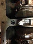
Had some trouble finding an M20 x 1.5 grub screw in the states to plug the feed next to the #2 main bearing. Finally had to order one from eBay (China).

I believe the Internet has more knockers than the cover of Electric Ladyland.
This project is interesting, you're clearly aware of the potential for misadventure but willing to see what is achievable.
This project is interesting, you're clearly aware of the potential for misadventure but willing to see what is achievable.
... the end of a long stroke motor usually occurs when the #4 rod throw becomes so occluded that the oil stops, ...
Yet, the pressure gauge tapped into the main gallery would give you a false sense of security even with that imminent failure.
True, I'm not sure any conventional sensor would be able to monitor sludge build-up in the rod throws. The idea, however, is the filter will filter the particles out of the oil so they never get centrifuged into the rod throws to begin with.
That was how I read it; the PRV and other motors of its era have hydraulically tensioned timing chains with fine mesh filters immediately prior to the tensioner housing - sludge and particle buildup occasionally blocks them, too. With lesser filtration it would happen so much faster and more often...
That would be Homer the Greek poet, I presume. The bloke who said, "And what he greatly thought, he nobly dared".
D'oh!!
That was how I read it; the PRV and other motors of its era have hydraulically tensioned timing chains with fine mesh filters immediately prior to the tensioner housing - sludge and particle buildup occasionally blocks them, too. With lesser filtration it would happen so much faster and more often...
Not sure about the PRV tensioner but many tensioners including the 5-main DS are not actually hydraulic, although often misinterpreted as such. The purpose of the oil feed to the tensioner is to oil the chain, not to pressurize the piston.
For example in the 5-main DS tensioner, the restrictor in the inlet to the tensioner body is about 0.5mm while the hole in the tensioner shoe is about 1mm diameter. The outlet hole has 4 times the area of the inlet, so there will be only negligible pressure. There will, however, be a steady dribble of oil out of the tensioner shoe right on to the chain.
A true hydraulic tensioner would be troublesome unless it had some sort of pressure relief valve on it. Otherwise transient oil pressure excursions could cause the tensioner to overtension the chain and then the ratchet would lock it in the overtensioned state.
The good news is that if the filter screen in the tensioner inlet gets completely plugged the tensioner still works, you just lose the integral chain oiling
Last edited:
Gotcha, I suppose I see them as "oil damped" rather than forcefully extruded. Renault had the same on the R16.
Oil-damped is a good term for it.
Project is back on track. I was stalled for a while waiting for the camshaft to come back from the regrinder and for the oil pump pinch bolt to come back from the plate shop (along with a bucket of other bolts and brackets). Meanwile I was rebuilding an SM transmission. Pinch bolt is in so I was finally able to verify the external pipe will thread into the pump and the oil pan does not interfere with the external pipe. Now I have some powder coating to do (oil pan and timing cover).
Cylinder head intake guides have been modified to take 9mm Mercedes oil seals on the intake valves. As soon as the head comes back from the shop, I can remove the dummy head (holding the liners in place) and install the real thing.
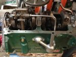
Cylinder head intake guides have been modified to take 9mm Mercedes oil seals on the intake valves. As soon as the head comes back from the shop, I can remove the dummy head (holding the liners in place) and install the real thing.

Hi Mark.
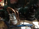
Copper has lousy fatigue strength and it work hardens. Eventually the engine vibration would cause the copper to work harden and then crack.
Copper has lousy fatigue strength and it work hardens. Eventually the engine vibration would cause the copper to work harden and then crack.
That Is a very nice job indeed!
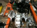
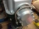
Further progress. I rebuilt the clockwork brakes (citrotech aluminum pistons, nitrile O-rings for LHM) and put new pistons (and LHM O-rings) in the gearbox cover. I replaced the 12 rubber bushings between the transmission and the front support (thread sealant on the M9 bolts that go through the case). Now, on to installing the hydraulic lines in the engine bay.....
