Resurrecting a Goddess.......Twice

suave faulksy

bet you can't wait to be rolling.

epilogue to your fuel pump re-co job.
i've pulled three apart so far.
a 009 for 74 914 1.8.
a 005 from a saab 99 ems (but also fitted to early 914s).
and a more ancient merc one with a slightly different port set up but more or less same as others.

they are all different inside in an evolutionary way. the 009 has the most compact electric armature and magnets.
i believe the 009 might be the last evolution of the type. i know a 010 is the inline type of the modern layout with 2 ports, one at each end.
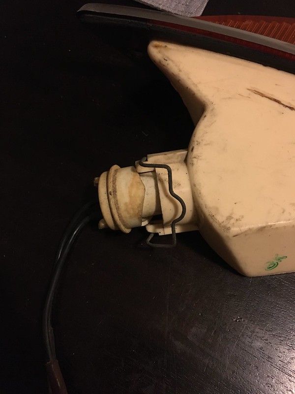
these pics are inside the 005.
bosch005G.jpg
bosch005Harrowed.jpg


i have a tip for anyone who wants to have a go like faulksy and pull one of these apart to fix it.
when you get down to the last bit, which is the electrical plug, what you should do is snip the wire to the electrical plug in the base of the unit. to do that you have to disassemble it more than faulksy did by driving out the little pin that holds the shaft of the motor assembly to the base of the port section. once you do that you can easily get inside the section that contains the electrical plug.
in all three pumps i have disassembled the electrical plug is wired into a rivet or stamped plug. you snip that wire and then you don't run the risk of tearing it out of the plug when you pull the plug out to do the last o-ring.

you can resolder it on reassembly.
(which i have yet to do).
 
Thanks Michael, good to see youre getting stuck in. You'll have to report back when you've got one back together and tested.

In an unrelated question, does anyone know why my drivers door will close easily if the star wheel is turned by hand before closing the door but needs to be slammed if the star wheel is left untouched?
 
I vaguely remember doing the same myself but everything has been in bits for years now. I'm sure you've worked it out yourself, but it kind of implies that - when you open the door - the star isn't rotating and clicking into a 'reset' position ready to close. Rotating by hand is a 'manual reset.

If there is anything valid in that (!) then might it be that the receiving part on the door is not quite in the right position to rotate the star enough when the door is opened? A small adjustment of the latch towards (or away from?) the star might be in order?
 
I think you're onto something there Budge, it may just be that ratchet inside the latch is worn out. I spent an hour adjusting the strike plate and it's as good as it's getting. I could loosen the hinge brackets on the frame and adjust the door that way maybe. Does anyone know of someone that may have NOS latches or remade ones?

In other news, new (to me) original 67-68 indicators with stainless steel surrounds turned up in the mail this week.

50844527367_8330d4ba9f_b.jpg


Bit of an improvement over the yellowed plastic ones that came in the boxes of parts in the background. Thinking it'd be an easy swap I set to with a screw driver to liberate the plastic ones from the wings. First challenge, the bulb holders for the 67-68 indicators must be different as the ones I have don't fit. The outer section with angled sides is a larger diameter than the hole. It's easy to modify and make it work but does anyone have a picture of what the 67-68 bulb holders look like?

50843739148_75d484f7d7_c.jpg

Why not just fit the stainless steel trim to the later plastic indicators I hear you say. Herein lies the second challenge. The stainless trim on the 67-68 indicators fits directly over the orange lens.

50844471046_9efeb012f5_c.jpg


The later plastic assemblies are the same as the older ones but with one important difference. Instead of the stainless steel trim, the factory bonded a second clear plastic piece with a silver backing to the orange lens. The net result is that the stainless steel trim doesn't fit.

50844471051_766b48dbfc_c.jpg
50844471041_f94dd8cd60_b.jpg


It turns out there is a reason the parts suppliers say you can't fit the stainless trim to the remanufactured indicator assemblies. They oversize the stainless steel trim to make it work. I'll break out a hack saw to modify the bulb holders later in the week and we'll be back in business.

Feeling thoroughly defeated by the vagaries of Citroen, I reluctantly reinserted the previously fitted indicators and turned my attention to other trivial matters such as working out where on Earth I had safely stored the paint disc and identification plate after taking them off 2 years ago. A thorough search of all boxes, jars, ziplock bags and the dining table turned up nothing which is a bit worrying.
 
ha I remember the front panels are sharp as under the indicators, I've had a few slices off them too. Worth warning others how nasty they can be.
 
Faulksy I ended up making this work on my DS.
I seem to recall using solvent to separate the plastic chrome bit from the coloured lens. May have also needed some trimming work.
I’ll have a look tomorrow and refresh my memory and revert!
 
There are two different suppliers of indicators - "Seima' and 'Axo' branded ones. The 'Seima' ones have push-fit bulb units and the 'Axo' ones have that fold-over clip. My car is a 68 with 'Axos'. You can see that the bulb holder slots into a groove at the clipping hinge points. They have caved crowns to help press the clip home. In these photos, on the indicator with the shiny clip, the bit of the body that holds the clip end has broken off, so the clip end is hanging loose. In the photo with three indictors, the grey one on the left is a Seima with a push-fit bulb holder. But is a different design to yours. All have s/s/ trim for Pallas cars.

IMG_6561 copy.JPG


IMG_6562 copy.JPG


IMG_6563 copy.JPG
 
Thanks guys, those photos are really helpful. It's amazing just how many minute details changed between model years. You'd think that the earlier indicators would be a drop in replacement. I'm thinking the most straight forward option is to modify the bulb holders although removing the "plastic chrome" is appealing as those lenses are in better shape.
 
Thanks guys, those photos are really helpful. It's amazing just how many minute details changed between model years. You'd think that the earlier indicators would be a drop in replacement. I'm thinking the most straight forward option is to modify the bulb holders although removing the "plastic chrome" is appealing as those lenses are in better shape.
There are some old indicator units upstairs at the shed. You’re welcome to see if the insides can be used
 
My indictor lens plastic was crackled and faded. I've managed to find one really good AXO replacement - good as NOS. Been looking for another for years.....
 
Thanks guys, with a bit of luck you'll see it at the concours in March. Just down to a thousand little jobs now which always seem to take the longest to sort out.

First up is finishing the temp gauge install. The gauge itself is working so the finishing touch is adding the graphic

50844527357_11724422d4_c.jpg


50868218616_706ce1cf34_c.jpg

The needle needed a bit of bending to straighten it out.

Next up is fitting the identity plate, having finally remembered where I'd safely stored it. 10 points to whoever can guess where. I'd just bout given up and was looking to see if any of the European supplies made them. Nice to have the original back.

50844445376_4bd9bde2ae_c.jpg

The fire had completely stripped all all the paint and tarnished the aluminium. A bit of black paint later and it's looking almost brand new. I may have gotten a bit enthusiastic with the steel wool while cleaning up the raised text.

50868316912_2719ab45d0_c.jpg


50868316907_0173b88aec_c.jpg

It wasn;t until trying to fit the plate that I realised a bunch of wiring had been threaded through the wrong hole in the firewall. Turns out all the wiring is supposed to go through a small hole just below the fusebox between the cabin vent and wiper motor. The identity plate itself is actually covering a hole. At least it was an easy fix with the instrument cluster out.

Following that was rebuilding the headlamp bulb holders with thicker gauge cable and new spade connectors. We should now have 12v all the way from the battery to the bulbs.

50810405047_283ef30f01_c.jpg

I'm sure they were originally a matched pair but the bulb holders are different on the left and right headlamps. One side is as simple as it gets and the other side not so much.

50810405587_998b790723_c.jpg


50810290686_f1e409f127_c.jpg


50810291921_6e454416a3_c.jpg

Turns out each bulb draws 4 amps so with the high beam and driving lights on the headlamps are drawing 16amps. If you can get all 6 bulbs burning you'll be at 24amps or over half the capacity of the alternator! That turned out to be a bit much for the old computer power supply I was using to test the headlamps.

Finally and somewhat maddeningly, the clutch slave is once more leaking LHM. It wasn't unexpected just not so soon after replacing the seal. The piston is 22.5mm dia and the nearest seal on hand was 22.4x3.55mm which leaves very little room for wear but does at least work for a while. There are at least 3 different seal sizes and configurations for the clutch slave and the only way to find out which one you need is to take the thing apart.

50876250078_971c84e455_c.jpg

The 1970 parts manual lists part no. ZD9506 000 U as the seal for the clutch slave fitted to EFI models which translates to a 22.7 x 3.6mm o-ring. given my piston is 22.5mm theres no way that will seal.

The same parts book lists part no. ZD 9503 700 U for a carry car which translates to a 18.4 x 2.7mm o-ring. This fits over the piston on the bench but gets badly gouged when installing the piston into the bore.

I'm thinking that the clutch slave has been replaced for a slightly later one which uses a 22.1 x 3.1mm o-ring. It definitely isn't one off of a DS23 as they generally have a larger piston and a teflon seal as well. Guess it's time to place another parts order as I managed to destroy the dust cover while trying to remove the clutch slave.

Seeing as I was playing with the clutch it seemed like a good moment to set up the BHV system properly. The centrifugal governor adjusted needed to be wound in 5 turns and the slow idle needs to be increased but at least the car will now move off from a standstill without stalling.

Stay tuned for another instalment of indicator woes
 
This weekend involved a quick systems check to see if all the electrics are working now that everything is connected. All systems worked fine with the exception of the passenger tail lamp.

50893319873_8cc431b1f3_c.jpg

Took the cover off to check the bulb and found all was fine. So out with the trusty multimeter to look for dodgy grounds. Annoyingly 2 things happened, the ground was fine and the negative multimeter probe broke. Before the probe broke I was able to tell that no power was getting to the parking lamp bulb. The parking lamp switch also tested fine.

Laying upside down in the passenger footwell this is the best view of the connections between the main and rear looms.

49921788608_e81a8d44e1_c.jpg

Another meter was sourced which revealed none of the appropriate wires had power. In a desperate attempt to figure out what the hell was going on I dug out the wiring diagram. Everything was connected where it should be. A cup of tea later and a sudden brainwave hit. See if you can guess what the problem was.....

50843713523_213ed60891_c.jpg

I didn't have any spare fuses on hand so swapped in one of the others which brought the tail lamp to life. Probably should have though of that earlier rather than spending 3 hours chasing wiring around the car....

Time for a bit of interior work fitting the padded upper sections to the doors.

50889249208_48e1b51680_c.jpg

An awl makes for a great way to pierce the leather and find the holes in the door. The top retaining piece went on pretty easily.

50894033321_7b664db556_c.jpg


50889960271_dc627fd479_c.jpg


50894033351_1f3ea09648_c.jpg

Getting the lower retaining trim on requires a bit of juggling to hold the piece and locate the holes for the screws whilst pulling wrinkles out of the leather. Getting the centre screw in first allows the leather to be stretched in each direction to get rid of the wrinkles.

Rather than cut the ends, i opted to fold the leather back under itself. Step one is to cut the stitching at the top edge so the leather can be pulled back to reveal the foam and canvas backing.

50894150297_0398de7bd2_c.jpg


50894150627_358fc8359f_c.jpg

Cut back the foam and push the leather back under using an icypole stick. Anything thin and blunt will do. I found that it was easier if the last screw of the lower retaining piece was removed and then put back once the edge was folded.

50894033301_f5723b8f74_c.jpg


50893319558_35b64bc67c_c.jpg


50894033776_e7fd7ec4dd_c.jpg

Does anybody have a handy hint for fitting the top stainless steel trim?

50893319538_9b4907bae0_b.jpg

Ready for door handles.

As a side note, I've managed to misplace the spring for the fuel filler door. Does anybody have a knackered fuel door knocking around or know of a supplier for the spring?
 
Hunting around for hints on fitting door handles, I've noticed that a lot of the factory upper door trims have a cutout in the hessian backing behind the handles. Does anyone think this is important?

1612495204587.png


1612495282851.png


1612495298961.png
 
Top