I may have, or access to, my old Paris Rhone regulator Steve. It was replaced by a modern style recently and the AE said he would hold on to the old for me. So now it should be still in his workshop, which won't be open again until after Easter, some time next week. Let me know if you still need one Steve and I will try to retrieve it for you. Ken

You are using an out of date browser. It may not display this or other websites correctly.
You should upgrade or use an alternative browser.
You should upgrade or use an alternative browser.
DS voltage regulator wiring
- Thread starter skp
- Start date
That would be brilliant Ken, fingers crossed not in bin! Thanks.
Not sure if you've seen this schematic. If the wiring around the alternator and voltage reg. is dodgy this should help sort it out.

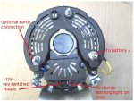
I'm sure you've been told all this before but here goes. The regulator is reasonably easy to test off the car:
connect BOB to +12v
connect a light between +12v and L terminal
ground is the metal tab on top of the rubber mount just above the L terminal.

With it all connected you should get +12V on EXC and the lamp should be on. If you connect R to +12v the lamp relay should open and turn the lamp off. With a BVH car this would also remove the ground for the starter switch.
The R terminal is connected to the rotor winding within the alternator and the small amount of current produced by it is what trips the lamp relay. Incidentally, I've found that dead diodes in the alternator will feed power to the R terminal without the alternator spinning and trip the relay. If you hear the relay click and the lamp isn't lit when you turn the key something is wrong.
Connecting the battery up backwards won't do anything to the regulator as the relay coils aren't polarised. It's more likely to have damaged the alternator.
I'm sure you've been told all this before but here goes. The regulator is reasonably easy to test off the car:
connect BOB to +12v
connect a light between +12v and L terminal
ground is the metal tab on top of the rubber mount just above the L terminal.
With it all connected you should get +12V on EXC and the lamp should be on. If you connect R to +12v the lamp relay should open and turn the lamp off. With a BVH car this would also remove the ground for the starter switch.
The R terminal is connected to the rotor winding within the alternator and the small amount of current produced by it is what trips the lamp relay. Incidentally, I've found that dead diodes in the alternator will feed power to the R terminal without the alternator spinning and trip the relay. If you hear the relay click and the lamp isn't lit when you turn the key something is wrong.
Connecting the battery up backwards won't do anything to the regulator as the relay coils aren't polarised. It's more likely to have damaged the alternator.
The wire into the green dash connector had no effect whatsoever, so I disconnected it put a free wire between the L into the green connector and tapped on the coil and bingo light went on and off accordingly. Thanks for the reg test info I will have a go when I'm in a good mood, struggling to get motivated due to heat!
Ok thankyou again Faulksy for the test, I followed your instructions,
wire to + from + on charger,
earth on reg to - on charger
test lamp onto L from +on charger.
wire from + on charger onto R.
result gives on off on lamp.
measured 12V at EXC.
so it must be in my wiring where the alt and Reg are being denied natural justice!
I am going to have to go through them all till I get a result. Ken ( sorry I wrote John....) I’m still keen on that reg if it is available as I don’t trust myself!
video result:
http://www.youtube.com/watch?v=651yPCS2NDM
Last edited:
Not sure if you've seen this schematic. If the wiring around the alternator and voltage reg. is dodgy this should help sort it out.
View attachment 104895
I'm sure you've been told all this before but here goes. The regulator is reasonably easy to test off the car:
connect BOB to +12v
connect a light between +12v and L terminal
ground is the metal tab on top of the rubber mount just above the L terminal.
View attachment 104896
With it all connected you should get +12V on EXC and the lamp should be on. If you connect R to +12v the lamp relay should open and turn the lamp off. With a BVH car this would also remove the ground for the starter switch.
The R terminal is connected to the rotor winding within the alternator and the small amount of current produced by it is what trips the lamp relay. Incidentally, I've found that dead diodes in the alternator will feed power to the R terminal without the alternator spinning and trip the relay. If you hear the relay click and the lamp isn't lit when you turn the key something is wrong.
Connecting the battery up backwards won't do anything to the regulator as the relay coils aren't polarised. It's more likely to have damaged the alternator.
This really useful info. Faulksy. I want to test my VR but I'm not sure I understand it. I'm struggling to visualise the connections. Is this it?:
Wire from a 12V supply to 'bob'
Another wire (with a light bulb) from the 12v supply to 'L'? (this is a bit I'm not sure about)
A grounding wire from the metal tab above the 'L' connection (and presumably back to the negative of the 12v supply?)
Using a meter, 'exc' should show 12v and the lamp should be on (is the meter being grounded to the tab above the 'L' terminal?)
"If you connect R to +12v the lamp relay should open and turn the lamp off." Do you mean "put a bridging wire from 'R' to the positive of the 12v supply"? Where is the 'lamp relay' ? Do you mean one of the coils/ gates inside the VR?
"With a BVH car this would also remove the ground for the starter switch." (not sure what this means or the significance of it?)
Subject to whether i've understood the connections correctly, can your instructions also be used to adjust the VR before it is fitted to the car - or can that only be done when in situ and with the alternator?
Hope you can advise.
Budge
I'm glad you found it useful. It took a fair bit of trial and error to get my reg. working properly as well but they are very robust devices. Answers to your questions are in italics.
Wire from a 12V supply to 'bob'
Another wire (with a light bulb) from the 12v supply to 'L'? (this is a bit I'm not sure about) yep that is correct
A grounding wire from the metal tab above the 'L' connection (and presumably back to the negative of the 12v supply?) yes, you may need to clean the tab to get a decent connection
Using a meter, 'exc' should show 12v and the lamp should be on (is the meter being grounded to the tab above the 'L' terminal?) either use the ground tab or the negative of your supply it doesnt really matter which.
"If you connect R to +12v the lamp relay should open and turn the lamp off." Do you mean "put a bridging wire from 'R' to the positive of the 12v supply"? Where is the 'lamp relay' ? Do you mean one of the coils/ gates inside the VR? yes, connect the R terminal to the positive of your supply. I would't do it for extended periods as i found the relay got rather warm. If you look at the picture i posted of the regulator without its cover, the lamp relay is the one closest to the camera and only has one set of contacts. The other relay is the actual voltage regulator which works by varying the voltage going to the field coils (EXC terminal) of the alternator. It does this by connecting either +12v or the large resistor on the underside of the reg.
"With a BVH car this would also remove the ground for the starter switch." (not sure what this means or the significance of it?) BVH or semi-auto cars have a starter inhibitor function which prevents the starter motor being engaged when the engine is running. The starter switch connected to the gear lever uses the charge lamp as its ground point so when the voltage reg. turns the charge lamp off it also removes the ground for the starter switch.
Subject to whether i've understood the connections correctly, can your instructions also be used to adjust the VR before it is fitted to the car - or can that only be done when in situ and with the alternator? I've never had the need to adjust one. There is a set of instructions in one of the factory manuals for doing so, I will see if i can find them. Pretty sure it needs to be on the car so that there is a load on the reg. otherwise it won't regulate.
Hope you can advise.
Budge
That's really helpful. I have a couple of Ducellier VRs. I'm going to have a fiddle tomorrow ")
Voltage regulator
Hi Steve
I now have the old regulator. Can you give me a call on 0407929073 for postage details, if you still need this one. It is Paris Rhone. Only identifying model marks are the numerals 808 on top RHS corner of the metal box cover.
Cheers
Ken
That would be brilliant Ken, fingers crossed not in bin! Thanks.
Hi Steve
I now have the old regulator. Can you give me a call on 0407929073 for postage details, if you still need this one. It is Paris Rhone. Only identifying model marks are the numerals 808 on top RHS corner of the metal box cover.
Cheers
Ken
Back again! Went out and took the hint from Chris and Don to purchase an alternator with regulator, care of Citrotech, ( prompt and good price, had to put a spacer on top mount) just looking at DSSMpassion diagram, pulled the dash out and loom as I want to see exactly where the red sleeve wire that goes from old regulator to dash light actually goes and ditch the mauve sleeve power to the old regulator. Also see where the power out of alternator is going. Yes it sounds crazy but given these wires were what Ithink was stuffing things up a few hours of unwrapping and rewrapping is not too scary.
Following the diagram then I'll ditch the white sleeve and hook the yellow out off alternator to red back to dash. Sound like a plan?
Just want some extra convincing!
Cheers Steven

Following the diagram then I'll ditch the white sleeve and hook the yellow out off alternator to red back to dash. Sound like a plan?
Just want some extra convincing!
Cheers Steven
Correct.
You only need two wires.
From B+ to battery + (obviously thick enough to carry some current)
From D+ to the red from the dash bulb.
If you don't connect the bulb, or if the bulb is blown, it won't charge. It provides the exciting current to the core.
Once it starts charging, voltage being equal at both ends, it goes off.
(Which just shows how... cilly... the whole light relay scheme is on the old regulator ;·)
You'll notice a (W) connector on the alternator too.
It's a square wave output, used for testing (oscilloscope) and rev counters on diesel engines.
Can the power out go straight to the battery?
B+ goes straight to battery +, yes.
It's as simple as it gets, really :·)
It's as simple as it gets, really :·)
thanks Don, I'm going to see where it joins up on loom and make decision whether it stays or gos straight over. Cheers
Well, if you had the old regulator, that is where it went.
The regulator then regulated it and sent it to the battery.
Now, this is already coming from a regulator, so...
The regulator then regulated it
and sent it to the battery.Now, this is already coming from a regulator, so...
You'll notice a (W) connector on the alternator too.
It's a square wave output, used for testing (oscilloscope) and rev counters on diesel engines.
I know we are talking about a BVM car here, but for what it's worth on a BVH car (at least using a CS-130 alternator) if you wire the tachometer output ("P terminal") through the switch loop of a DIN relay, then wire the wand to the starter relay through the NC terminals of the relay, you will restore the starter interlock function.
I know we are talking about a BVM car here, but for what it's worth on a BVH car (at least using a CS-130 alternator) if you wire the tachometer output ("P terminal") through the switch loop of a DIN relay, then wire the wand to the starter relay through the NC terminals of the relay, you will restore the starter interlock function.
Very interesting. Good for us, but the Aussies might have a tough time finding a CS130. The CS144 is physically too large.
Very interesting. Good for us, but the Aussies might have a tough time finding a CS130. The CS144 is physically too large.
I was really thinking that if someone wanted to take a chance with the Citrotech alternator, it might also work as long as it can handle the same tachometer load as a CS130...
I was really thinking that if someone wanted to take a chance with the Citrotech alternator, it might also work as long as it can handle the same tachometer load as a CS130...
Does that alt (I think it's an Iskra) even have a tach output? Tach signal on a D is measured at the coil. I'm of the thought you could simply set up a second relay that takes it's on/off from the lamp. It's all 12V with no regulation.
I’m dismantling my lovely Christian Fahrig loom and the wire that should go from regulator (red sleeve) to the green connector on dash goes all by itself, and thick diameter to around about the ignition switch with a female bullet connector. WTF? Did he make this for a BVH I am starting to wonder, it’s bizarre.
I’m dismantling my lovely Christian Fahrig loom and the wire that should go from regulator (red sleeve) to the green connector on dash goes all by itself, and thick diameter to around about the ignition switch with a female bullet connector. WTF? Did he make this for a BVH I am starting to wonder, it’s bizarre.
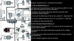
Who knows, but with the internal regulator alternator supplied by Citroen Classics UK that might be correct, Darrin supplies a wiring diagram which in your case would be useful.
This is the Citrotech alternator version that you have in English possibly some help? From the dssmpassion link, sorry about the poor qaulity just a screen shot after google translate.
Cheers
Chris