DS voltage regulator wiring

if you are looking for an original regulator I bought a new old stock one ( with the 4 pins) from some mob in Belgium. If keen I can rummage through receipts to give you their details, cost about $150 with postage from memory.

DOOP see you have just ordered one, there was one on ebay in US for silly money...
 
Have you tried one of these, John? I haven't had occasion to try one yet. They look like they're dead-nuts simple to hook up.

We've had a chat about these (or similar) in another thread some time ago - it would be interesting to follow this through and see a definitive wiring diagram for both BVM and BVH.

I was fortunate in that Richo set me up with a very straightforward alternator swap with inbuilt regulator, but this issue crops up quite frequently as the original regulators are falling over.

Cheers
Chris
 
It's pretty straightforward, actually.
The OE regulator has a built in ~8V relay that is normally closed. When the alternator is operating properly, the relay opens.
On BVM cars the only thing the relay does is ground the light.
On BVH cars the relay grounds the light AND the wand for the starter, thus it has to have fairly low impedance contacts. That's it for the difference in the wiring diagrams.

Modern regulators do not have a dedicated light relay (or transistor). Instead, they go from a first state that is a high impedance ground (which is enough to illuminate a dash indicator light but not enough to operate a starter relay) to a second state that is +12 so there is no current and thus the dash indicator light is extinguished. The high impedance ground is the reason you cannot use a modern regulator with a BVH unless you do something with the starter wand.
 
Back onto this topic as I am stumped why my Ducellier alternator is not charging, on start the dash light comes on and won’t go off. I have replaced the old regulator with a correct new and unadjusted Ducellier regulator. I gave up waiting for the auto electrician to test it because he didn’t quite get what the connections on the reg were for even after I handed him a wiring diagram, hoping to get advice from you guys on what to do next. I have a new loom with the only difference being I had to add an extra wire for the starter off the brown lead out of the ignition to the battery to get the starter to work, starter solenoid on starter direct to battery. I can’t help thinking the L lead from the reg or the Bob lead are not going where they should, or the positive off the alternator are headed somewhere not correct. Measuring off the positive on the alternator led to only 12.8V so nothing happening, but the auto electrician tested the alternator and he reckons it is working. Where to start? Frustrated because this is the last real issue with finishing the car!
Cheers
Steven
 
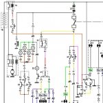
Let's see if this is any help. . .

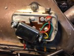
This was my regulator before I upraded to an alt with internal reg.

17734d1309678116-greenblood%92s-d-very-special-rejuvenation-2009-regulator2.jpg


The Brown sleeve wire is part of the front loom, and goes to 'L' on the regulator. (shows as red on the diagram? it has a branch that runs to the dash light).

The wire to the left goes to ground and is a 'fly' wire (not part of the main loom).

The white sleeve wire [Bc] also a fly wire connects 'R' on the reg to 'R'on the alternator.

The Yellow sleeve wire (J) also a fly wire connects from 'Exc' on the reg to 'E' on the alternator.

The Mauve sleeve wire goes to 'BOB' on the regulator, not seen in my pic.

You will have a black wire providing 12+ to the alternator, should be part of the front loom.
Also an earth from the alternator, this will be a fly wire and not part of the loom.

attachment.php

#15 is the regulator and #12 is the alternator.

Hopefully between the above pic and the diagram you should be able to work things through. . .

Edit: Check this diagram, it shows the Brown sleeve wire runs to the starter switch, might have something to do with you needing to add an additional wire that may not be required??

Holy smoke we need HRE :burnboun:

attachment.php


Cheers
Chris
 

Attachments

  • Reg Alt.JPG
    Reg Alt.JPG
    26.2 KB · Views: 484
  • Reg starter.JPG
    Reg starter.JPG
    54.4 KB · Views: 540
thanks Chris. That brown sleeve connection is one point where I think my wiring is arse up. TBC.

Calling all Bills! This is not a drill.
 
The first thing to check is, are you getting 12V on the BOB wire when you turn the ignition on? If not, then your ignition switch, or the wire from your ignition switch to the BOB terminal may be bad. Your indicator light is working, so we know that part of the loom is OK. The only other two wires are the R wire and the EXC wire. You can easily check for continuity between the regulator and the alternator terminals with an Ohm meter. Finally, if everything checks out, start the car and, with a volt meter on the battery, attach a jumper from the positive terminal of the battery directly to the EXC terminal on the alternator. At a fast idle, the voltage should jump to about 15V. If not, then the problem is the alternator and not the voltage regulator.

Regarding the brown wire, third dash BVM cars have a different starter switch and loom than third dash BVH cars. In BVH cars, a wire from the battery-mounted relay is grounded by the starter switch. In BVM cars, the starter switch sources positive voltage to the starter solenoid in the start position.
 
Last edited:
While we are on the subject, to answer Bill's question, yes. I have successfully installed a miniature electronic VR inside the original can. The photo is my first attempt. On later renditions, I mounted the electronic VR upside down from the way it is shown here, so I could get to the trimming pot used to adjust the target voltage.

.electronic voltage regulator in OE can.jpg
 
quick question is 32 actually on the ignition switch?

the wire I added from the brown wire on the ignition switch goes to the battery and I think it should go to the bob connection.
 
No. It is the BVH wand switch. The wiring diagram that was posted previously is for a BVH car. #16 is the battery-mounted relay (which is not present in third dash BVM cars). The switch loop of the battery-mounted relay is grounded by the wand switch through the voltage regulator.
 
Thanks John, do you know where the L connection on the reg travels to on a late manual wiring loom?
 
No. It is the BVH wand switch. The wiring diagram that was posted previously is for a BVH car. #16 is the battery-mounted relay (which is not present in third dash BVM cars). The switch loop of the battery-mounted relay is grounded by the wand switch through the voltage regulator.

Thanks John for the correction, back to the drawing board I see #32 is deleted for BVM. . .

This should be the correct diagram for BVM which now shows 8 connections at the ignition switch and includes the Brown sleeve wire Steven is talking about. #32 is still shown but is now part of the ignition switch (#32 no longer in the legend of parts).

attachment.php


Steven this shows 'L' as going directly to the ignition dash light (green multiplug Mv sleeve wire).

Cheers
Chris
 

Attachments

  • Basic RHD wiring.JPG
    Basic RHD wiring.JPG
    94.6 KB · Views: 503
have you got the full diagram Chris?

I have the brown out of switch going straight to battery but maybe it should patch into the main black lead from battery to switch. Also wondering if I have the wrong regulator but doubt it as they should do the same thing?
 
Last edited:
All regulators are the same whether BVH or BVM. The only difference is whether the regulator grounds just the charge light or grounds both the charge light and the BVH wand starter switch.
 
I have an alternator which according to an auto electrician is cranking, and a light on the dash which will not extinguish, a quick test showed the alternator is at 12.8 volts. And the battery is draining so I am wondering what the fugazi is wrong.

You have to remember Bill this is someone who buys reverse lights, installs them and then after testing over and over realises they didn’t come with bulbs.
 
Last edited:
Top