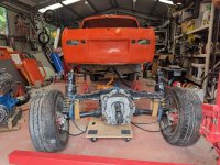
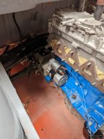
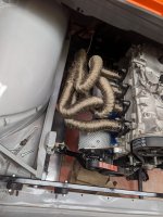
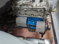
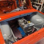
Engine is in, only one catch, it's not quite straight and even after rewelding the mounts on the rear cross member it's still not right as everything is mounted on rubber.
Will this be corrected by the tie bars? Or will I need to remove everything and fix the mounts on the suspension cross member. I slackened off all the mount bolts to attempt to correct it.
Will this be corrected by the tie bars? Or will I need to remove everything and fix the mounts on the suspension cross member. I slackened off all the mount bolts to attempt to correct it.
")