I know I asked already, but your new "trusted brand" pads aren't directional?

You are using an out of date browser. It may not display this or other websites correctly.
You should upgrade or use an alternative browser.
You should upgrade or use an alternative browser.
Brake experts ~ please expose yourself!
- Thread starter RINGER
- Start date
You did & they are not. I'm sure sorting out the levels, torsion bar adjustment & consequently the weights on each axle & each hub the brakes will be fine.
I have asked Gerry in a PM, but am into it right now if anyone can help please?
Gerry said "Loosening the nut lowers the car and tightening raises it."
Anyone have a guesstimate of how much the vehicle raises or lowers on either one castellation [1/6] or full 360* turn of the nut ~
Seems currently I need:
LHR raise from 228mm to 264mm
RHR raise from 235mm to 264mm
If you can help I would much appreciate.
Once done will lower & re-check front before doing anything up there.
Many thanks guys, John
We know we are close, so 'feel' what effort is needed on jack handle & whether this has increased after the adjustment so as to be equal on both sides. We know the measurements we need to change in #43How do you measure the 'feel' with a jack? I would think you might have some chance of a DIY measurement using a crowbar under the hub and a known mass on the end. If you can do this repeatably and know the location of the fulcrum point, you could probably work out the maths for leverage, but it would be easier to look at relative deflection of the lever. You'd have to ensure L&R on the same beam are very close or the difference will affect the other end when it's back on all four wheels..
Given this car is 70+ years old now, also consider that the torsion bars may be beyond their best or could even have been swapped.
If it doesn't work out, consider this as a fallback:
https://www.aussiefrogs.com/forum/index.php?threads/146622
LHR 36mm
RHR 29mm so ~
Just like torque 'feel' some can get so close to spot on. Not so important with this older stuff that is not modern torque turn & more. JG.
Last edited:
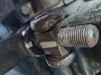
Well off the deck & this is what I've done:
LHR raise from 228mm to 264mm =36mm so did 3 full turns 18 hex flats special black tool was a breeze.
RHR raise from 235mm to 264mm = 29mm so did 2.5 turns 15 hex flats modified Total Tools wrench worked on a nut that had been worked over, more than once in the 70 years before me!
Right or wrong it's the right ratio so we maybe making progress & just might be a lucky guess.
The ring end is worthless.
Attachments
Well done did the LHR & RHR now measure after road test L 240mm & R 245mm. Strange less turns more lift?
Still pulls left, less severe ~ also gave a good burnishing over about 3km all wheels felt similarly hot after. So application is about right will get heat temp pointer gun out, if I can find.
More to come tomorrow then I'll also do the front.
Monday back to the RBT & check again.
Time for a 1698 from Uncle Dan's gr8 drop of Kentish Strong Ale, come to think of it may have a couple!
Hi John Earlier you did say the front end is not adjustable. This is not true. While the camber is not adjustable, the caster is and if the front end has been reconditioned for new top bushes the pins may have just been assembled without knowing that they need to be set correctly for the camber. So possible they are uneven side to side as usually need to be withing 0.5 deg. The old manual has the adjustment:
ADJUSTMENT OF CASTER ANGLE (See Drawing 91)
Having adjusted heights under hull at front and rear (see Operation 151, paragraphs 1, 2 and 3),
and with tyres at correct pressure, place vehicle on a HORIZONTAL surface or on an.elevating
service platform.
Remove-greasers from upper and lower link arms (these greasers are for lubricating ball joints).
Fit parts of gauge MR.1767 (using greasers to fit braakets) and position as indicated on
Drawing 91. The plumb line must fall against the appropriate gauge mark according to the vehicle
being checked.
If correct reading is not obtained, correct the caster angle (see Drawing 45). Slacken clamp
bolts (10) of the upper link spindle, and with the aid of a nut and lock nut sorewed on the
threaded portion, or a flat spanner size 23, turn spindle in the direction necessary to carry the
upper link arm into the position required to give correct gauge reading.
Having obtained the correct setting tighten clamp bolts (10). Repeat the procedure for other
side of axle.
THE CORRECT CASTER ANGLE IS l"30?, PLUS OR MINUS 0'15'.
A quick check could be done after your torsion bar adjustment, by using a digital level vertically on some suitable parts.
Jaahn
FRONT AXLE-•, ’P 45
. . .
-SECTION ON CENTER LINE OF UPPER LINK-
 ,
,
ADJUSTMENT OF CASTER ANGLE (See Drawing 91)
Having adjusted heights under hull at front and rear (see Operation 151, paragraphs 1, 2 and 3),
and with tyres at correct pressure, place vehicle on a HORIZONTAL surface or on an.elevating
service platform.
Remove-greasers from upper and lower link arms (these greasers are for lubricating ball joints).
Fit parts of gauge MR.1767 (using greasers to fit braakets) and position as indicated on
Drawing 91. The plumb line must fall against the appropriate gauge mark according to the vehicle
being checked.
If correct reading is not obtained, correct the caster angle (see Drawing 45). Slacken clamp
bolts (10) of the upper link spindle, and with the aid of a nut and lock nut sorewed on the
threaded portion, or a flat spanner size 23, turn spindle in the direction necessary to carry the
upper link arm into the position required to give correct gauge reading.
Having obtained the correct setting tighten clamp bolts (10). Repeat the procedure for other
side of axle.
THE CORRECT CASTER ANGLE IS l"30?, PLUS OR MINUS 0'15'.
A quick check could be done after your torsion bar adjustment, by using a digital level vertically on some suitable parts.
Jaahn
FRONT AXLE-•, ’P 45
. . .
-SECTION ON CENTER LINE OF UPPER LINK-
Many thanks Jaahn, I'll check that out that area which has not been altered but seems devoid of wear & properly lubed.
It does steer really straight so caster is not an apparent issue, but I'll see what it read when the last wheel alignment was done & take note for next time.
Most of this modern computerised stuff won't hook up properly & the grease monkeys don't understand actual wheel alignment or what's going on & particular an old car like this.
Camber is small & good I've checked with a level.
Should have seen the look on the guy at Bob Jane's face when I asked for a front end wheel alignment.Most of this modern computerised stuff won't hook up properly & the grease monkeys don't understand actual wheel alignment or what's going on & particular an old car like this.

It's always pulled up straight on the brakes too.

did you get charged half price for 1 wheel ,?
did you get charged half price for 1 wheel ,?
There's no adjustment at all, only the drag link to keep the pitman arm in the correct relationship at the straight ahead.Simple is as simple does.

LHR & RHR now 246mm each LHF & RHF are 252mm each.
Checked camber all around is 0* on all wheels.
Will re-check caster, toe & steering lock adjustment after RBT tomorrow afternoon, before any more adjustments. JG.
Checked camber all around is 0* on all wheels.
Will re-check caster, toe & steering lock adjustment after RBT tomorrow afternoon, before any more adjustments. JG.
We are all waiting to hear if its improved at all !!
Especially me! It is always good to sort things out & learn along the way. Hopefully these type threads help others & that is how valuable this forum is. To think we nearly lost it?
You clearly have more brake pressure on the front left. Nevermind the rear for now, the rear end of the car does maybe 10% of the braking.
So, the measured deceleration is showing as greatest opposite to those wheels supporting the greatest weight?
The weight distribution hasn't changed much via the 'feel' method. Is 'feel' misleading?

The weight distribution hasn't changed much via the 'feel' method. Is 'feel' misleading?
Only adjusted the heights @ this stage.So, the measured deceleration is showing as greatest opposite to those wheels supporting the greatest weight?
The weight distribution hasn't changed much via the 'feel' method. Is 'feel' misleading?
View attachment 212058
1. May take Alan's advice & ask Ken @ Accurate Suspension in Woodridge about setting up all 4 wheels
2.Re-check toe & caster when able to get in.
3.Check mechanical, calliper's operation & pad contact for equality.
4. Also hydraulic hard lines as all flexible are new.
Called Alan's recommendation in Woodridge http://www.accuratesuspension.com.au/ & booked in Thursday week....JG.
Great advice coming through from af era experience.my first encounter with car pulling/locking brakes was at Renault aust,Richmond w/shop around50 years ago with an r10,after front calipers were o/hauled and still pulled the late Ian Amsing put it on our wheel scales we had and found one weak front spring not exerting the downward force as opposite side.fast forward 40years at bus depot driver complaing of l/f wheel locking up,bus eventually broke front sway bar(over 40mmdiam) .some one had adjusted left rear air bag ride height too high subsequent excess load put on r/front suspension remedy..replace leaking l/r air bag and rest heights..all good.looking outside the box and thinking what if is always there in diagnosing faults…jim