The manual says that the spiral grooves should be "right hand at the synchromesh dog and left hand at the gear." What it doesn't say is which way is the Z axis, moving from the end of the gear toward center, moving from the center of the gear outward or from the gear toward the dogs. Anyway can you confirm that the bushes in the above photograph have been installed correctly? To me they both look left hand....

You are using an out of date browser. It may not display this or other websites correctly.
You should upgrade or use an alternative browser.
You should upgrade or use an alternative browser.
1954 Traction 11BL Transmission Overhaul
- Thread starter citroenthusiast
- Start date
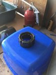
Here are some better photos . Gear end:

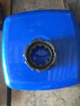
Dog end

If not, perhaps that explains why the bushing moved outward instead of the usual inward motion....
Dog end
If not, perhaps that explains why the bushing moved outward instead of the usual inward motion....
Unuseable on that side and one of the main faults caused by a loose pinion shaft nut. Buy some new ones! Using those will never allow the pinion conic depth to be accurately set!Some scuffing of the half locking collars caused by the loose pinion nut, but not too bad. View attachment 127369
Look at the gears themselves and you will see small holes drilled at the root of the teeth. The action of meshing squeezes oil into the space between the bushes. The spirals carry the oil along the bush to the thrust washer ends.Here are some better photos . Gear end:View attachment 127381
Dog end
View attachment 127382
If not, perhaps that explains why the bushing moved outward instead of the usual inward motion....
The bushes are out. They are identical and both appear to be left hand helix. I think someone may have installed two 500.523 bushes instead of one 500.523 and one 500.893

I just had another thought. If the other side of those half locking collars are not grooved then you could do what I used to do when parts were really hard to come by forty years ago. Insert them with the smooth side on the bevel pinion side so that the fixed splined gears have a good surface to lock up tight against. The smooth side is forced against the rear shoulder of the groove in the pinion shaft when full torque is applied to the pinion shaft nut!Unuseable on that side and one of the main faults caused by a loose pinion shaft nut. Buy some new ones! Using those will never allow the pinion conic depth to be accurately set!
Can you photograph the other sides please?
Last edited:
The back sides of the half locking collars appear to be in pretty good shape. I had thought about reversing them so the splines bore on the good sides, however, if my local supplier has them I will probably replace.

Do you agree with my observation that my second gear cluster appears to have two left hand bushes?
Do you agree with my observation that my second gear cluster appears to have two left hand bushes?
Yes! But check the top gear bush! May be they put the wrong handed bush in there instead????????The back sides of the half locking collars appear to be in pretty good shape. I had thought about reversing them so the splines bore on the good sides, however, if my local supplier has them I will probably replace.View attachment 127388
Do you agree with my observation that my second gear cluster appears to have two left hand bushes?
Last edited:
Top gear bush is also left handed and has an oil groove so not misplaced from the second gear cluster... You can see the top gear in my 3:36 pm post from yesterday (except you may have to adjust since I am UTC -7)
I made one by filing ramps into a worn synchro hub centre. If you take the hub apart do it inside a heavy plastic bag!!!!!!!Continuing disassembly of the box, after noting Shane struggled with the snap rings holding the main shaft bearings in position, I was pleased to find that with the proper snap ring pliers, I was able to get the rings off without too much difficulty.
View attachment 127347
The rest of the box came apart pretty much as Shane described, including dropping all of the balls from the reverse idler thrust bearings into the bottom of the box. I had some difficulty with the plunger that locks the second gear cluster splined washer in place until I realized that the plunger is depressed radially into the shaft rather than axially into the gear cluster. The manual is ambiguous regarding which way the plunger is depressed (however, it would have been clear had I remembered the parts diagram).
View attachment 127350
The bushings on the second gear main shaft cluster have not moved, or at least have not moved as profoundly as on Shane's transmission. The oil hole is still visible. The cluster does rock a bit on the shaft and I can fit a .022 inch (.5mm) feeler gauge between the bushing and the spline. I can also see a distinct wear pattern at the outermost 10mm or so of the bushing.
View attachment 127348
I suppose I will replace the bushings as a precaution unless .5mm of play is clearly acceptable. The manual seems to suggest using a boring bar rather than a reamer to bore the bushings so that the gears will run true on the shaft even if the bushing bore in the gear cluster itself is not true to the gear. When the manual says to rectify the OD of the gear using a mandrel sized to match the worn bushings are they suggesting that you take a skim cut off the gear itself?
The reverse idler and the third gear on the main shaft both have a bit of rock to them about .2 - .3mm clearance according to my calibrated hand. The bush inside the third gear shows some sign of scoring and/or burned oil.
View attachment 127349
Again I will probably replace the bushes unless .3mm of clearance is acceptable.
I was able to get the synchro to move with my fingers a bit in each direction once it was off the shaft. Possibly it was just gummed up from non-use. I did not push it far enough to lock over in either direction, fearing the balls and ramps would go flying across the garage. Not having a false hub (tool MR 3025), I am not sure I want to disassemble it at all. Possibly I can just soak it in solvent and blow out with air? Alternatively, I have a 3D printer at my disposal. If I had a drawing of what tool MR3025 looked like I could possibly make one out of ABS.
I made one by filing ramps into a worn synchro hub centre. If you take the hub apart do it inside a heavy plastic bag!!!!!!!
I should have posted a picture of your tool. I don't know how you would get it back together without that!
Shane, I think you did post a photo and anyway, that is basically what the manual tells you to do to make tool MR 3025. It assumes of course that you have a bunch of knackered T/A boxes laying around and can sacrifice a synchro to make the tool....
I just had another thought. If the other side of those half locking collars are not grooved then you could do what I used to do when parts were really hard to come by forty years ago. Insert them with the smooth side on the bevel pinion side so that the fixed splined gears have a good surface to lock up tight against. The smooth side is forced against the rear shoulder of the groove in the pinion shaft when full torque is applied to the pinion shaft nut!
Can you photograph the other sides please?
It looks like reversing the half locking collars (500.533) may be my only option. Franssen doesn't list them, CTA has them listed but out of stock. Not sure who else to try.
I would clean up & re-use but here is somewhere else & there are a few others as well.
https://www.pat2d.com/gearbox-pinions-shafts-and-forks.htm
https://www.traction-owners.co.uk/spare-parts-list/
https://www.pat2d.com/gearbox-pinions-shafts-and-forks.htm
https://www.traction-owners.co.uk/spare-parts-list/
Last edited:
You can lap the better side on a surface plate ( or a pane of glass) to improve the quality of the faces.I would clean up & re-use but here is somewhere else & there are a few others as well.
https://www.pat2d.com/gearbox-pinions-shafts-and-forks.htm
https://www.traction-owners.co.uk/spare-parts-list/
As long as I am going to have to order parts from Europe I figured I would at least try to get a handle on what I will need for the differential. If I understand what Gerry explained to Shane correctly, my differential is under meshed by about 0.6mm.

The clearance between the upper sun gear and the face of the housing with the existing celeron washer is about 0.2mm.

If I am getting all this, it means I should increase the thickness of the washers behind the planet gears by 0.3 mm (half of the 0.6 mm under mesh). This will decrease the clearance of the sun gear by (0.6 sin 45) or about 0.45 mm on each side. At that point I play with the thickness of the Celeron washer under the bottom sun gear until it is on the verge of binding then repeat with the upper sun gear until the upper sun gear and washer are flush with the surface of the housing?
The clearance between the upper sun gear and the face of the housing with the existing celeron washer is about 0.2mm.
If I am getting all this, it means I should increase the thickness of the washers behind the planet gears by 0.3 mm (half of the 0.6 mm under mesh). This will decrease the clearance of the sun gear by (0.6 sin 45) or about 0.45 mm on each side. At that point I play with the thickness of the Celeron washer under the bottom sun gear until it is on the verge of binding then repeat with the upper sun gear until the upper sun gear and washer are flush with the surface of the housing?
that's a better way to measure it. I was assembling it and measuring the movement in the shaft!As long as I am going to have to order parts from Europe I figured I would at least try to get a handle on what I will need for the differential. If I understand what Gerry explained to Shane correctly, my differential is under meshed by about 0.6mm.
View attachment 127408
The clearance between the upper sun gear and the face of the housing with the existing celeron washer is about 0.2mm.
View attachment 127410
If I am getting all this, it means I should increase the thickness of the washers behind the planet gears by 0.3 mm (half of the 0.6 mm under mesh). This will decrease the clearance of the sun gear by (0.6 sin 45) or about 0.45 mm on each side. At that point I play with the thickness of the Celeron washer under the bottom sun gear until it is on the verge of binding then repeat with the upper sun gear until the upper sun gear and washer are flush with the surface of the housing?
Actually, I realized that since the under mesh is 0.6 on the radius, I should increase the thickness of all of the planet gear washers by 0.6mm.
I think I needed to make mine quite a bit thicker (from memory) ... the planetary gear shafts were quite worn .... so I couldn't really set any of that.