What is the shim material, Frans?

You are using an out of date browser. It may not display this or other websites correctly.
You should upgrade or use an alternative browser.
You should upgrade or use an alternative browser.
The dry sump Gordini motor.
- Thread starter Frans
- Start date
Simon.........the hang-ons will be replaced by all he pipes going to and from the motor.
John....I use tin snips to cut it. I think the copper gaskets are annealed as well and that is good to seal where you might have unevenness in the surface.
SZ.....It is steel shims.
Frans.
John....I use tin snips to cut it. I think the copper gaskets are annealed as well and that is good to seal where you might have unevenness in the surface.
SZ.....It is steel shims.
Frans.
Your good with the tin snips!!!
John....I use tin snips to cut it. I think the copper gaskets are annealed as well and that is good to seal where you might have unevenness in the surface.
Frans.
I find good scissors work best on shim. Tin snips leave a slight bent edge. I got a pair of excellent Sidchrome scissors for Christmas. They are brilliant. But Frans with the quality work you are doing you don't need my input.
Sidchrome scissors sound good. Is there a model number please? I might indulge....
Started this weekend playing with the dry sump motor again and I got to make the scraper plate and a push rod!
I had this idea in mind to make the scraper plate from Teflon. It can take the heat and if there is touching any parts then it won't create metal filings. It was a bit of imagineering on the mounting method of the plate. At first I thought of drilling and tapping into the main bearing mounting beams that runs across from the side of the block to the center , but decided against that because I think it will make the beam weaker. So the final idea came to mind and I am now using it as the "gasket" on the one side and the other side will have a real gasket. There are 3 x 3mm small roll pins to keep the scraper plate in the exact position and when tightening the sump the roll pins will be able to slide deeper and allow the sump to sit tight on the Teflon. I drilled and tapped the bigends and made little plates holding the other end in as in the last photo. We will see if this works.


Then I started on the push rods. These will be made out of 1/4" stainless steel tubing. Johan had a few working so I will say it is going to be ok. As we all know, the lighter the valve train the less spring tension is required for more rpm's. When I finished the first one I weighed it and the compared it with others. A genuine long G push rod weighs 35g, the ones I made from Titanium (solid) weighs 25g and the new one from stainless steel is hollow and weighs 25g as well. Pleasant surprise because now my push rods will cost me about $9.00. The damaged one is the Titanium one middle is original and then the SS one. The weight gain is 28.6%. New Edit. 27/04/2021.
Pushrods will be from Titanium. Ignore above.


I had this idea in mind to make the scraper plate from Teflon. It can take the heat and if there is touching any parts then it won't create metal filings. It was a bit of imagineering on the mounting method of the plate. At first I thought of drilling and tapping into the main bearing mounting beams that runs across from the side of the block to the center , but decided against that because I think it will make the beam weaker. So the final idea came to mind and I am now using it as the "gasket" on the one side and the other side will have a real gasket. There are 3 x 3mm small roll pins to keep the scraper plate in the exact position and when tightening the sump the roll pins will be able to slide deeper and allow the sump to sit tight on the Teflon. I drilled and tapped the bigends and made little plates holding the other end in as in the last photo. We will see if this works.
Then I started on the push rods. These will be made out of 1/4" stainless steel tubing. Johan had a few working so I will say it is going to be ok. As we all know, the lighter the valve train the less spring tension is required for more rpm's. When I finished the first one I weighed it and the compared it with others. A genuine long G push rod weighs 35g, the ones I made from Titanium (solid) weighs 25g and the new one from stainless steel is hollow and weighs 25g as well. Pleasant surprise because now my push rods will cost me about $9.00. The damaged one is the Titanium one middle is original and then the SS one. The weight gain is 28.6%. New Edit. 27/04/2021.
Pushrods will be from Titanium. Ignore above.
Last edited:
Nice Frans.
I have an ignorant question. How do the lower parts of the cylinder walls get lubricated with the dry sump arrangement?
Nice pushrods!
Cheers
I have an ignorant question. How do the lower parts of the cylinder walls get lubricated with the dry sump arrangement?
Nice pushrods!
Cheers
Hi All,
John, I can't answer you. My mind tells me that there is the same amount of oil dripping down from the head and that is splashed up to the cylinder walls. My wind-age tray prevented splash feed in any case.
Now this engine is the one that came out of the Matra. I have moaned and bitched previously about the poor workmanship of whoever built the engine as a race engine. The Matra was prepped for a race car hence the plastic windscreen. The pistons in there were unknown and so I saved them for the dry sump engine. When it came to sorting out, these pistons were pushing the compression ratio up to about 20:1. It would never have worked.
When I checked the head the exhaust ports were huge, and tapered to the inside. With the extractor being standard the exhaust gases would have been restricted with a huge square orifice that would prevent flow. That is why I had to make inserts that fitted in there to bring the ports back to standard as in the Matra restoration thread. With the engine in and "ready" to race 3 of the 5 extractor studs were stripped! Etc etc.
The block were cleaned and I found the cam bushes were shot. I made a special tool for the removal and refitting of that and it was line bored. The line boring went horribly wrong and one bush was oval, so I had to do it over again. The engine number plate was removed but the rivet holes weren't closed. Imagine the oil leak when the rotation of the cam forced the oil through the 2 rivet hole! At last everything were replaced and I started and made the the scraper plate for the crank that was in the Matra. Lightened and knife edged.
Then on completion I took the components in for balancing so that I can start on the bottom end. I got a call from the engine balancer saying that the flange of the crank where the flywheel bolts to, is not running true. I had the crank crack tested and yes, the crank was cracked. So in the end there were basically nothing that I could re-use from the Matra engine.
I found another crank that wasn't perfect and it needs a regrind on all the journals. So Ebay helped out and the bearings arrived today. I will now assemble the rods and mains and take the block in for grinding as per rod and main-bearing dimensions. (semi Blueprinted).
And that is the reason the dry sump engine is so far behind schedule.
Regards. Frans.
I admire your perseverance, Frans. Keep up the good work.
Keith
Keith
It really shows you can't trust many engines unless you rebuild them yourself or really know the rebuilder, doesn't it. What a pain.
Saw Harry yesterday at the Rear Engine Car Day in Perth - he's looking well, as is the Alconi R10!
Good luck with it as the right bits finally come together.
Saw Harry yesterday at the Rear Engine Car Day in Perth - he's looking well, as is the Alconi R10!
Good luck with it as the right bits finally come together.
Then I started on the push rods. These will be made out of 1/4" stainless steel tubing.]
Frans, how did you replicate the knobs on the end of the SS rods, or are they the original ends pressed in to the end of the SS tube?
ta
Frans, how did you replicate the knobs on the end of the SS rods, or are they the original ends pressed in to the end of the SS tube?
ta
Hi Alexander,
I have collected a lot of non crossflow pushrods with time. I measured the ID of the stainless tube and then I turned the heads off in the lathe as in the picture so that they are a press fit into the tube.
The only drawback of this is that you have to do 16 non crossflow pushrods to make 8 G pushrods because the G has ball ends on both sides.
Regards, Frans.
Last edited:
Nice work Frans. I have a question however. Have you considered how you will clean out the tank? It will eventually get rubbish in it. One of the things I've learned with racing 205's is the need for easy cleaning. Thus when I made my tank I started off with a flange and then worked up and down from there.
Attachments
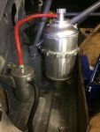
Hi Peter.
I am glad you asked the question. The 4th thread on page 1 shows the tanks and the drain plug at the bottom. I reckoned that the tank could be cleaned by flushing it with some diesel or petrol. Do you think that the drain plug is too small?
The bottom of the tank is a little cone shaped for the grid or sludge to settle in with the outlet to the pump a little higher.
Regards. Frans
Thanks for the info Peter and the reason. the tanks are still with Ross and I can't remember the sizes although it won't be far off.
To add to the delay........ The rod bearings that arrived is STD and not 0.25mm. So there we go again.
Regards
Frans.
To add to the delay........ The rod bearings that arrived is STD and not 0.25mm. So there we go again.
Regards
Frans.
Hi All,
At last it all came together. Everything for the bottom end is now ready for balancing. Conrods, pistons, crank is blueprinted to bearings, pressure plate pulley and flywheel will be at the balancer tomorrow and I might just get them back before Christmas. I have just put the flywheel on a killer diet and it weighs in at 3.678 kg. Attached photos of my doings and screwings.


Regards
Frans
At last it all came together. Everything for the bottom end is now ready for balancing. Conrods, pistons, crank is blueprinted to bearings, pressure plate pulley and flywheel will be at the balancer tomorrow and I might just get them back before Christmas. I have just put the flywheel on a killer diet and it weighs in at 3.678 kg. Attached photos of my doings and screwings.
Regards
Frans
Last edited:
Hi All, At last it all came together. Everything for the bottom end is now ready for balancing. Conrods, pistons, crank is blueprinted to bearings, pressure plate pulley and flywheel will be at the balancer tomorrow and I might just get them back before Christmas. I have just put the flywheel on a killer diet and it weighs in at 3.678 kg. Attached photos of my doings and screwings. Regards Frans
Very nice Frans. Love your scales. Nothing to go wrong with those electronics, and very accurate!
Hi All,
At last it all came together. Everything for the bottom end is now ready for balancing. Conrods, pistons, crank is blueprinted to bearings, pressure plate pulley and flywheel will be at the balancer tomorrow and I might just get them back before Christmas. I have just put the flywheel on a killer diet and it weighs in at 3.678 kg. Attached photos of my doings and screwings.


Regards
Frans
Very nice Frans. Love your scales. Nothing to go wrong with those electronics, and very accurate!
More great work there Frans.
Yes my mum has a set of scales like that, been around longer than I can remember.
I forgot to ask Frans: do you not get the crank and the flywheel balanced as a unit? Not a criticism at all, just a curious question. I've only been there once, with my R8 engine which I had balanced before I built it back in 1988. The shop insisted on doing flywheel, crankshaft and clutch as an item. I've since needed a new clutch, so it is not balanced now as a unit, but it certainly doesn't feel different, but I rarely exceed 5,000 rpm of course.
Hope you and yours have an excellent Christmas.
Hope you and yours have an excellent Christmas.