The dry sump Gordini motor.

Frans

Well-known member
VIP Paid Subscriber
1000+ Posts
Fellow Frogger
Joined
Sep 24, 2001
Messages
1,944
Location
Auckland
I’m building another engine for the race car and I will stick my process and progress up here for anybody to follow if they are interested. Your approval or disapproval might become interesting. If I am not mistaken I think it is only the Peugeot guys that have gone this way here on AF.

It happened a long time ago when the then doyen of Gordini racing cars, Brian Evans, told me “you will never make a reliable G motor unless you go dry sump”. Now that was like an “I dare you” to me. Brian’s cars were really quick and everybody envied him and his daughter Cindy’s cars. Geckoeng will know him very well.
So I was lucky enough to build reliable motors with wet sumps and for the first time in a long while somebody overtook Cindy down the pit straight at the Midvaal track in ZA.

Now I am going Brian’s way and doing a dry sump. There is a start in the other thread but I will post some pictures here to re-start the thread.

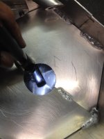
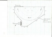
The sump shape is like that because I believe it will catch and collect the oil more effectively. With the “wall” or “vertical” on the one side the oil that will be scraped off by the scraper will run down into the gutter quicker to be sucked back to the tank. It was also very easy to make by closing it up with only 2 plates welded in. I leak tested it with BrakeClean and all is OK. In the drawing is the position of the scraper.

This image will show the wall I am talking about.

Regards Frans.
 

Attachments

  • Scan_Pic0015.jpg
    Scan_Pic0015.jpg
    426.5 KB · Views: 155
  • sumpa.JPG
    sumpa.JPG
    735.1 KB · Views: 156
  • sumpc.JPG
    sumpc.JPG
    547.4 KB · Views: 156
Last edited:
Fascinating Frans. Busy cave you've got there! :)

I presume there's plenty of oil still spraying and splashing around to lubricate cylinder walls.

Cheers
 
John I hope so. There are so many running successful that I will assume it to be OK.

Frans.
 
Oil tanks.
The oil tanks are still in production although almost done. It will get its final touches when installed.

According to the clever guy “Google” and A Bell the oil tank must be about 2 x higher than its width. I want to mount mine just in front of the engine on the cross member. That will limit the height because it must fit under the rear parcel shelf. Pushing the dimension limits, it worked out that to hold 10 liters it is going to be almost the same width as height. Only 5 l of oil will be in it so it will be half full.
The top plate that allows the oil to swirl/flow flatly so that it can de-aerate becomes a baffle to limit the oil splash. Ross and Johan agreed on the design and I started to make 3 of them. Because I have a hand operated bender and not a roller, I decided to make them hexagonal instead of round. It must have at least a certain “roundness” in the shape so that the returning oil that is full of air bubbles can flow around the top of the tank to be de-aerated before it runs back into the pickup area. I also wanted the bottom to be conical so that impurities and sludge can settle there and be drained. So the bottom is not flat and the oil is picked up about 30mm from the bottom. Here are some of the parts that needs to get welded.

IMG_0726.JPG


Weld in aluminium oil filler caps is very expensive so me and Ross went to my favourite shop “PickaPart” and we found the ideal filler caps for only $12 each ex Toyota. So here is the latest results in the tanks assembly line. See the oil filler cap?

IMG_0777.JPG


This image shows the dual function baffle plate/de-aerator plate welded in just below the return pipe.

IMG_0778.JPG


This photo shows the outlet at the bottom of the tank.

IMG_0777.JPG


The last items to be done is a breather tank that will sit piggy back on the main tank with its own drain.

Regards.
Frans.
 

Attachments

  • IMG_0780.JPG
    IMG_0780.JPG
    281 KB · Views: 126
Last edited:
Hi Frans,
You are getting serious now, but to spend a lot of time and money on building top motors that only last a short time is unproductive. And so to make a motor produce power and last is an added amount of work, but very fruitful at the end of a season.

Brian was very right in using a dry sump, he said it came from modern tyres that put far more G into the cars, and hence moved the oil more and for longer. Can be seen on Hans-Peter Wiebe hillclimb car, how long he is in the corner with power full on, and it is stuck to the road. An ordinary Gordini would have blown the bearings half way.

I watch in anticipation,
Ray
 
Last edited:
Frans, back to your "wet sump but reliable" claim: what did you do?

All I've done with the standard sump pans on my R8, Djet & 4CVG is weld in a semicircular dwarf wall around the pickup to help keep oil there on right handers. It works nicely enough on even vigorous road work & only starts to starve on roundabouts. (How I love roundabouts!) I assume that you've gone further & internally roofed the pan. Or what?

cheers! Peter
 
Hi Peter,
I think I understand what you did, it makes sense but I would take the chance to say it's good for spirited driving. The problem comes in more so with the ZA car because that was a full blown track car with 10" Michelin slicks. The G's I do not know but I have checked my NZ car and with semi slicks I exceed 1G two to three times a lap. Then you have many corners that is long 180 deg sweepers.

What I have done is to divide the sump in 3 segments with baffle plates that can hinge one way only. Oil can flow towards the pump but not away from the pump. This is mainly for hard braking and acceleration. Then I have a plate covering the sump so that the oil is below it. Right hand bends are taken care of the plate because the oil can only run up to it and not through it. Lefthanders are the problem because there has to be a big hole of about 100mm dia for the pump pick-up to go through when fitting the sump on the right hand side of the sump. To overcome this problem I have fitted a "lid" to the pump itself. This is carefully cut with all the tips and gullys of the pump shape in so that it is covering every little corner as good as I can do my fitting. I also cut an inspection/manhole in the lower end of the straight side of the sump so that I can see through it so that when the sump is fitted this "lid" seals properly. When all is good and I am satisfied I close this hole up with a can that holds an extra liter of oil. This adds to the volume of the center compartment that houses the pickup.
With the oil that seeps through the cavities (the fitting cannot be 100% but I reckon it is close to 90%) on long bends the level will drop but because there are more oil in that compartment the level drops slower/less than what it would have without the added inspection hole cover.

Sump with out cover.
Sump1.jpg


Sump with top plate. Note the extra canister that covers the inspection hole.
Sump4.jpg


Sump with oilpump that has the "lid" fitted to it.
Sump2.jpg


Regards.
Frans.
 
Last edited:
A question that I might ask to all those developing "G" forces and oil starvation simultaneously in car engines is how does an aerobatic aircraft fly a/. inverted for extended periods and b/. repeatedly under forces of up to 5 or 6 "G" in any plane? (Up down sideways not cessna/piper.) Engine failure in such an aircraft results in significantly more drama than an engine failure in a car. Perhaps we should be studying aircraft dry sump technology?
 
Hi Peter,
I think I understand what you did, it makes sense but I would take the chance to say it's good for spirited driving. The problem comes in more so with the ZA car because that was a full blown track car with 10" Michelin slicks. The G's I do not know but I have checked my NZ car and with semi slicks I exceed 1G two to three times a lap. Then you have many corners that is long 180 deg sweepers.

What I have done is to divide the sump in 3 segments with baffle plates that can hinge one way only. Oil can flow towards the pump but not away from the pump. This is mainly for hard braking and acceleration. Then I have a plate covering the sump so that the oil is below it. Right hand bends are taken care of the plate because the oil can only run up to it and not through it. Lefthanders are the problem because there has to be a big hole of about 100mm dia for the pump pick-up to go through when fitting the sump on the right hand side of the sump. To overcome this problem I have fitted a "lid" to the pump itself. This is carefully cut with all the tips and gullys of the pump shape in so that it is covering every little corner as good as I can do my fitting. I also cut an inspection/manhole in the lower end of the straight side of the sump so that I can see through it so that when the sump is fitted this "lid" seals properly. When all is good and I am satisfied I close this hole up with a can that holds an extra liter of oil. This adds to the volume of the center compartment that houses the pickup.
With the oil that seeps through the cavities (the fitting cannot be 100% but I reckon it is close to 90%) on long bends the level will drop but because there are more oil in that compartment the level drops slower/less than what it would have without the added inspection hole cover.

Sump with out cover.
2cqjxcp.jpg


Sump with top plate. Note the extra canister that covers the inspection hole.
2evqb1l.jpg


Sump with oilpump that has the "lid" fitted to it.
3009lc7.jpg


Regards.
Frans.

Nice, thanks. I especially appreciated the picture of the (hairy) canister covering the inspection hole.

cheers! Peter

Post Scriptum: At the time of making the above observation, the photo in question was not of the sump pan but was a nice profile shot of a pleasant looking woman. Frans has since remediated the bungle

:-((
 
Last edited:
Some dry sump aircraft engine sumps appear to be simply scavenged by piston ring blowby pushing collected oil into the oil reservoir. Pressure and one way valves, extra piping come together with weighted oil pickups to remove oil from inverted rocker covers etc, and the factor determining the length of time an engine can remain operating at full power inverted (in some cases more than 15 minutes) is the capacity of the reservoir. So, if you are running out of oil in a corner or two, you need a bigger oil tank.
 
The Lycoming horizontally opposed aerobatic aircraft engines which are fitted to almost every unlimited category aerobatic aircraft use a simple system by Christen industries and is as simple as an oil separator and a ball valve using a wet sump. +&- 10 G all day long.The engine will never run out of oil.I had a One Design aerobatic aircraft with this simple system,never had an issue..KISS principle!
 
Nice, thanks. I especially appreciated the picture of the (hairy) canister covering the inspection hole.

cheers! Peter

That is why I have a sticker on the each of the front doors: "Built not Bought"

Regards
Frans
 
Oil pump mounting.
The oil pump is a very old unit although still in a good condition. I opened it and there are very little score marks. It is a 3 stage pump, 2 for scavenging and 1 for pressure with its own adjustable pressure relief valve. It is chain driven and not belt driven like the new ones today. In mounting the pump I had to do a fair bit of Imagineering and scrapped the first model. It is now ok and adjustable for tensioning the chain. In working out how to do the pump drive I made an extension that will mount on the front of the crank and bolted down to the crank. I faced another few issues because one would like to be double safe that the gear is tight in case there is slippage. That meant I would like to have the drive on a keyway and I cannot cut a keyway that size (5mm). I made use of old timing gear components, that is for the drive and driven gear and an old timing chain. So to overcome the slippage possibility without a woodruff key, I drilled and tapped M5 holes and screwed M5 grub screw in to become the “woodruff key”. I thought it a very good substitute and easy to make. That finalized the drive and it shouldn’t slip at all.

This is the extension.
IMG_0783.JPG


This is the grub screw that is acting like a woodruff key slotting into the crank pulley.
IMG_0784.JPG


And then the oil pump drive gear slots into the second grub screw.
IMG_0786.JPG


And this is the end result.
IMG_1307.JPG


Regards,
Frans.
 
Last edited:
The Lycoming horizontally opposed aerobatic aircraft engines which are fitted to almost every unlimited category aerobatic aircraft use a simple system by Christen industries and is as simple as an oil separator and a ball valve using a wet sump. +&- 10 G all day long.The engine will never run out of oil.I had a One Design aerobatic aircraft with this simple system,never had an issue..KISS principle!

As a matter of interest Brian, what is the longest you had the plane inverted? I only ask because an unnamed person piloted himself and I in a non dry sump Decathalon from take off to the Aerobatic area inverted for some 10-12 minutes. Reading the POH after the event (he thought it was a dry sump) produced a lump in both our throats! The engine showed no apparent ill effects!
 
Kim and anyone else who wants great info on dry sumping to actually gain hp by the man who discovered how and why, Grumpy Jenkins, email me at pandabiz@163.com and I will send you a 54 meg file.
 
Kim, the longest I would fly inverted in the One Design was about 5 minutes and that was just for fun,in competition aerobatics inverted flight is normally restricted to a few seconds.I found the fuel would start to vent after long periods.See One Design and Corby Starlet Aeros Utube.
I think part of the reason Lycoming engines will handle such abuse is they are big bore slow revving (2500rpm) engines.They also have nice big oil galleries!
 
Thanks Damien!

Machining of the sleeves.
After the sleeves were rebored I had to machine the outers to get it to fit in the block. The bottom skirt had to be decreased slightly and then I had to take a big amount of steel off where the sleeve fouled against the engine block. This is 1400 sleeves fitted into a 1255 Gordini block. That is why it is not just a straight swap. I had them in the lathe and this was the easy part. Now I will check them with a straight edge to see how far below the block they are and then buy the appropriate thickness shims so that the protrusion is what I want when they are placed under the sleeves like the paper seals originally.

IMG_0752.JPG


IMG_0753.JPG


Frans.
 
Last edited:
Thanks Damien!

Machining of the sleeves.
After the sleeves were rebored I had to machine the outers to get it to fit in the block. The bottom skirt had to be decreased slightly and then I had to take a big amount of steel off where the sleeve fouled against the engine block. This is 1400 sleeves fitted into a 1255 Gordini block. That is why it is not just a straight swap. I had them in the lathe and this was the easy part. Now I will check them with a straight edge to see how far below the block they are and then buy the appropriate thickness shims so that the protrusion is what I want when they are placed under the sleeves like the paper seals originally.Frans.

Great photos Frans. Neat work too of course...

I might have asked this but what do you use to seal the bottom of the sleeve with the steel shim fitted.
 
Hi Frans,

Will your oil pump chain drive not need some form of lubrication?, or will greasing it as on a bike chain be sufficient?

Henry
 
Top