R8 upgrade project

Valve Springs.

Hi WB,

OK, ill have a read.

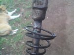
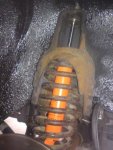
I've never read any material on what is an acceptable amount of free area - 1/16" is 1.6mm then times the 5 intercoil areas give 8mm - excessive maybe?

Thankyou for the book tip - unfortuantely ive never read one novel in my life (how uncultured) but i can chew through car books / tech stuff no probs!

BR
 
BR,
My interpretation is that as long as there is the gap between one or two coils there should be no binding ?

Phil Irving is of the old school but I can imagine his ideas are still current.
 
Driving Position Project

Time has passed the R8 seats by - still comfortable but in a lounge chair sort of way - mine are in great condition but they put me to sleep.

The cabin is not spacious by any means and i really wanted to get the driving position correct - or maybe moreso to my liking.

The steering wheel angle and the pedals are offset so the drivers seat needs to be facing them in my opinion - i also wanted to lower the drivers seating position and increase the recline to account for the depth of the pedals versus the steering wheels position.

This creates a whole range if sliding trajectory issues coupled with the fit issues of the small cabin.

It was possible with the momo's - just - at every extremity the seats are brushing pillars, themselves, poking into recesses etc but it all works.

I used some 3.5mm aluminium plate angle and cut the floor profiles into that so they slide into the orginal seat mounting rails in the floor - no need to drill or cut. Two holes drilled at the floor just infront of the cross member for the front mounting. For the 5/6 points of the harnesses i used the original seats rear bolt area with the captive popped out - the harness point reinforcing plate is cut down to fit around the crossmember underneath but this leaves it reversible to original.

The rear harness mounts on the parcel shelf vertical as close to the seam as poss and are plate reinforced. All other original seat belt points are used for the harness mounts.

One of the pics shows the angled offset for the drivers seat compared to the passengers seat.

The new seating positions feel great and also provide the room for fire extinguishers to the right of the driver / passenger and also hydraulic handbrake between the seats - plus room for the modified shift setup i am mounting.

These should pose no probs for rego. The essence of ADR22 (i think that is it) says that any pre adr vehicle that has its seats changed then the replacement should comply with the essence of adr22 which is that there is a backing area considered to act like a head rest / restraint.

Only prob is it also mentions that the seats must be parallel to the centreline of the vehicle so thats a bit contentious ...
 

Attachments

  • DSC01635.jpg
    DSC01635.jpg
    19.4 KB · Views: 412
  • DSC01634.jpg
    DSC01634.jpg
    19.3 KB · Views: 401
  • DSC01647.jpg
    DSC01647.jpg
    17.6 KB · Views: 376
  • DSC01645.jpg
    DSC01645.jpg
    21.1 KB · Views: 410
  • DSC01644.jpg
    DSC01644.jpg
    24.2 KB · Views: 380
  • DSC01643.jpg
    DSC01643.jpg
    18.1 KB · Views: 389
  • DSC01642.jpg
    DSC01642.jpg
    14.2 KB · Views: 384
  • DSC01641.jpg
    DSC01641.jpg
    26 KB · Views: 385
  • DSC01640.jpg
    DSC01640.jpg
    21.6 KB · Views: 408
  • DSC01639.jpg
    DSC01639.jpg
    29.3 KB · Views: 430
  • DSC01648.jpg
    DSC01648.jpg
    26.1 KB · Views: 382
Momo's looks great, when I started looking for seats I decided on normal racing seats as the momo's looked as they wouldn't fit. Went with the same idea you had with the bar at the back on which the seats mount. I only used steel instead of Aluminium.
But it looks great and the new seat positions feel excellent as I'm sure yours does as well.
 

Attachments

  • 100.JPG
    100.JPG
    98.7 KB · Views: 412
Time has passed the R8 seats by - still comfortable but in a lounge chair sort of way - mine are in great condition but they put me to sleep.

The cabin is not spacious by any means and i really wanted to get the driving position correct - or maybe moreso to my liking.

The steering wheel angle and the pedals are offset so the drivers seat needs to be facing them in my opinion - i also wanted to lower the drivers seating position and increase the recline to account for the depth of the pedals versus the steering wheels position.

This creates a whole range if sliding trajectory issues coupled with the fit issues of the small cabin.

It was possible with the momo's - just - at every extremity the seats are brushing pillars, themselves, poking into recesses etc but it all works.

I used some 3.5mm aluminium plate angle and cut the floor profiles into that so they slide into the orginal seat mounting rails in the floor - no need to drill or cut. Two holes drilled at the floor just infront of the cross member for the front mounting. For the 5/6 points of the harnesses i used the original seats rear bolt area with the captive popped out - the harness point reinforcing plate is cut down to fit around the crossmember underneath but this leaves it reversible to original.

The rear harness mounts on the parcel shelf vertical as close to the seam as poss and are plate reinforced. All other original seat belt points are used for the harness mounts.

One of the pics shows the angled offset for the drivers seat compared to the passengers seat.

The new seating positions feel great and also provide the room for fire extinguishers to the right of the driver / passenger and also hydraulic handbrake between the seats - plus room for the modified shift setup i am mounting.

These should pose no probs for rego. The essence of ADR22 (i think that is it) says that any pre adr vehicle that has its seats changed then the replacement should comply with the essence of adr22 which is that there is a backing area considered to act like a head rest / restraint.

Only prob is it also mentions that the seats must be parallel to the centreline of the vehicle so thats a bit contentious ...

Seats look great, good job
wayne :D
 
Quick Shift Project

Facing the facts the original shift seems to me to be less than idyllic.

It is too far forward - orientated moreso to allow the seats to go all the way forward to form a bed and also for a seating height higher than the new one.

The throw is also quite long - and in general is way far away from the steering wheel.

I wanted to bring the shift closer to driver / steering wheel and reduce the throw.

As i would be increasing the height i had to take that into consideration as i was aiming for a 5" throw.

My calcs came out for a 50mm increase in length between the pivot ball and the shift rod connector.

59 Floride had been kind enough to help out with a another shift lever for the project (thanks mate).

So cutting the lever below the pivot ball and then cutting another 50mm section from the top of the lever to insert i then ground down a high 3/8 high tensile bolt leaving enough meat to make it an interference fit.

The 50mm piece i drilled slightly oversize to fit over the ground down bolt snuggly and then drover the pieces together then welded the pieces (slowly in small beads as they you cannot put too much heat in the pivot ball as it will melt!)

The connector end must sit in the same place so the pivot ball assembly needs to be raised the height of the extension - i didnt have cad/cam machine sitting arouns nor a big billet of aluminium so i made the spacer pucks out of 25mm sheet mdf - they work fine.

The floor need some modification to allow the shifters new higher pivot angle - basically it needs the round hole to be about 10mm diameter wider and squared off.

Once mounted i used some copper to to make a shift shaft template then bent up the steel tube to the final shape - assembled that and welded it on, then fitted with some a/c pipe insulation and topped with sparco shift knob.

Pics 1698 shows the shifter in the 1st/2nd gate line.

Pics 1704 and 1705 show the throw between the 3rd / 4th gate - about 5" - sits in a great pos next to the wheel.
 

Attachments

  • DSC01703.jpg
    DSC01703.jpg
    36.2 KB · Views: 422
  • DSC01702.jpg
    DSC01702.jpg
    28.8 KB · Views: 395
  • DSC01698.jpg
    DSC01698.jpg
    20.1 KB · Views: 434
  • DSC01697.jpg
    DSC01697.jpg
    24.3 KB · Views: 417
  • DSC01694.jpg
    DSC01694.jpg
    48.8 KB · Views: 411
  • DSC01691.jpg
    DSC01691.jpg
    31.4 KB · Views: 394
  • DSC01690.jpg
    DSC01690.jpg
    34.9 KB · Views: 403
  • DSC01689.jpg
    DSC01689.jpg
    55.1 KB · Views: 437
  • DSC01688.jpg
    DSC01688.jpg
    52.9 KB · Views: 409
  • DSC01693.jpg
    DSC01693.jpg
    63.3 KB · Views: 418
  • DSC01704.jpg
    DSC01704.jpg
    28 KB · Views: 408
  • DSC01705.jpg
    DSC01705.jpg
    27.5 KB · Views: 380
  • DSC01706.jpg
    DSC01706.jpg
    29.2 KB · Views: 386
Well maybe not physical HP but it certainly adds 20HP of bling to the engine bay.

QUOTE]

Something though that will add Hp is the removal of the socks on the trumpets, and making up an airbox for the trumpets to suck from preferably with a fresh air intake. I proved this on a dyno many years ago with a stroker rally Datto 1600. Everyone on the rally scene use socks, but to their detriment, besides which I think they only stop rocks, and certainly disturb the flow into the trumpet. It was quite a gain for a simple mod, I think 8Hp at the wheels.
 
Had you considered using a boxer engine from a Subaru WRX rather than a BUSA? Adapter plates are readily available here in the states to connect them to VW Bus transmissions, the 4 beam one is sturdy, if you don't mind only four forward gears. I haven't done the engineering, but I have considered using this along with Porsche brakes and axles in the rear.

Those motors easily put out 250hp and are available all day long for a fair price.

Has anyone done this?
 
Oil Management Project Part 1

The original 16TS sump has a smallish oil capacity, protrudes too low and has no real ability to heat sink the oil to the air efficiently.

So alloy alpine style sump and a new set of big ends while inside.

All seems easier than the execution.

Firstly the engine mount bar curves under the front of the sump so it has to be removed enough to allow access.

Then the new sump flange is 10mm - the old sump is pressed steel 1.25 thick so the bolts are not long enough - and they are M7's! - like the rarest easily available bolts - supercheap dont keep M7 but the new high tensile bolt section at Bunnings did - but only in one size at 35mm long so i had to use the nuts to provide the torque on the blind ones (wasnt going to cut so many short!).

An yes i could have gone to Coventry fasteners etc but that was too much hassle.

Next was the oil pickup - it was way to long - like 21mm or so. Mecaparts seems to list a 12mm spacer for the sump but even that was not going to help and also with the engine mount curving under i would have had to cut a recess out of that etc.

So i cut it and shut it to the new depth required.

The baffle plate looks effective with the hinged one way entry points. It did required to be "relieved" with a hammer slightly around the pump area (you can see in the pics my "relieving"). It also required the relief valve split pin to be cut down and also because the dipstick is on the other side i had to holesaw the baffle plate (yes could have change the sides in the block of the dip but i didnt think i could make it seal well enough).

One thing was when i went to remove the baffle plate the allen key bolts were not tight nor were locktighted in.

To finish this bit i had to cut a small portion off the dip stick (the original low / full still remained on the stick) and then remarked it with baffle height, lowest crank protrusion point and sump flange marks.

Also while in there i changed the big ends - the crank pins looked excellent, micro'ed up to virtually factory width and they are on standard size.

So that takes care of part one of the oil project and gives me a heap more clearance under the rear.
 

Attachments

  • DSC01657.jpg
    DSC01657.jpg
    23.4 KB · Views: 337
  • DSC01667.jpg
    DSC01667.jpg
    39.9 KB · Views: 330
  • DSC01665.jpg
    DSC01665.jpg
    39.4 KB · Views: 318
  • DSC01663.jpg
    DSC01663.jpg
    32.5 KB · Views: 332
  • DSC01660.jpg
    DSC01660.jpg
    36.4 KB · Views: 327
  • DSC01659.jpg
    DSC01659.jpg
    40.4 KB · Views: 345
  • DSC01656.jpg
    DSC01656.jpg
    21.9 KB · Views: 346
  • DSC01655.jpg
    DSC01655.jpg
    33.6 KB · Views: 346
  • DSC01652.jpg
    DSC01652.jpg
    41.9 KB · Views: 384
  • DSC01650.jpg
    DSC01650.jpg
    39.3 KB · Views: 385
  • DSC01669.jpg
    DSC01669.jpg
    45.9 KB · Views: 336
  • DSC01670.jpg
    DSC01670.jpg
    40 KB · Views: 328
  • DSC01671.jpg
    DSC01671.jpg
    38.1 KB · Views: 339
  • DSC01672.jpg
    DSC01672.jpg
    34.5 KB · Views: 334
Subaru Engine

Hi Gordinowitz,

subaru motor will not fit without some major mods such as cutting out half of the rear rails.

also i think its too heavy for the rear - these are my thoughts, not saying it cant be done or is bad.

also yes seen 8's before using vw transmissions as its easy to get them to hold some big hp's -

the easiest renault trans fit for bigger hp is a speedbox 364 - utlising 16ts crown etc - is good for 250HP. check out the tech on it at Steve Swans site http://www.8gordiniworkshop.pwp.blueyonder.co.uk/

BR
 
Ignition Panel Project

My ignition barrel is a bit dicky and sort of gets stuck occasionally on the start cycle.

It also is a piggy to turn back around to the off pos and is not really that accessible for quickly trying to start the car etc after a spin / stall etc - especially when strapped into those momo's.

So i quickly built up a little aluminium plate ignition panel and it also makes a facia plate for the brake proportioning valve - some might say its a bit wanky - and you are probably right but its pretty functional and my 10 year says its looks cool.

Mentally im probably not more than 10 anyrate so i'm in good company ....
 

Attachments

  • DSC01764.jpg
    DSC01764.jpg
    35.7 KB · Views: 445
  • DSC01762.jpg
    DSC01762.jpg
    36.7 KB · Views: 425
  • DSC01758.jpg
    DSC01758.jpg
    47 KB · Views: 407
  • DSC01755.jpg
    DSC01755.jpg
    36.5 KB · Views: 472
  • DSC01737.jpg
    DSC01737.jpg
    38.5 KB · Views: 398
  • DSC01736.jpg
    DSC01736.jpg
    41.2 KB · Views: 439
  • DSC01756.jpg
    DSC01756.jpg
    35.8 KB · Views: 395
Oil Management Project Part 2

The alloy sump will help cool the oil but under very hard driving in hot conditions i wanted further help.

I will never run an oil cooler without an oil thermostat - the oil will be too cool and increases bore wear dramatcially as it is not thin enough to squirt / flick onto the bores properly and oil has a designed operating temperature to reduce sludge formation etc etc etc.

I also wanted to move to a remote filter for two reasons - one is that i can run the filter in the vertical plane and two is that i can fit any size filter i wanted.

So i bought a whole heap of parts and cobbled together the system in my own style as usual - for some reason nothing off the shelf will do for me.

I fitted two 3mm thick right angle aluminium bars to not only provide the oil cooler / remote filter mounting points but also to tie the rear upper guards area of the car together as bracing.

I used a Mocal sandwich plate style oil cooler thermostat and then a remote filter housing on that.

Braided lines and speedflow connectors top it off - i must admit it is soooo much fun doing braided lines.

The best part about this setup is that the oil pressure seems to come up almost immediately on start - i think the combination of a vertical filter and also that when the oil cooler drains back into the sump when the engine is off allows an oil level where the pump is submerged but when running the oil level sits below the crank protrusion. Really unsure but it all seems to work very well.

This gives me an oil capacity in the system of over 5L.

I also switched to a 20x1.5 thread in the remote filter housing to give me a bit more choice in filters - i think the one it runs now is a Renault 25GTX.

I suppose if it does nothing else it looks trick?
 

Attachments

  • DSC01725.jpg
    DSC01725.jpg
    32.7 KB · Views: 405
  • DSC01729.jpg
    DSC01729.jpg
    43.8 KB · Views: 410
  • DSC01727.jpg
    DSC01727.jpg
    54.3 KB · Views: 473
  • DSC01723.jpg
    DSC01723.jpg
    50.4 KB · Views: 455
  • DSC01722.jpg
    DSC01722.jpg
    53.2 KB · Views: 432
  • DSC01721.jpg
    DSC01721.jpg
    39.5 KB · Views: 404
  • DSC01720.jpg
    DSC01720.jpg
    35.5 KB · Views: 402
  • DSC01718.jpg
    DSC01718.jpg
    38.9 KB · Views: 427
  • DSC01716.jpg
    DSC01716.jpg
    50.6 KB · Views: 435
  • DSC01632.jpg
    DSC01632.jpg
    27.3 KB · Views: 470
  • DSC01730.jpg
    DSC01730.jpg
    37.3 KB · Views: 413
  • DSC01731.jpg
    DSC01731.jpg
    49.5 KB · Views: 426
  • DSC01733.jpg
    DSC01733.jpg
    47.5 KB · Views: 484
Oil Management Project Part 3

Well not really a project but it finishes this area.

Its just the oil catch can and breather routing and finishing off all the pipe work.

The catch can just screams jappo bling.

The engine bay looks quite trick now and is ceratinly a long way from when i started on the car in July.
 

Attachments

  • Stephanie-0077.jpg
    Stephanie-0077.jpg
    58.6 KB · Views: 392
  • DSC01775.jpg
    DSC01775.jpg
    52.9 KB · Views: 411
  • DSC01777.jpg
    DSC01777.jpg
    47.3 KB · Views: 427
  • DSC01773.jpg
    DSC01773.jpg
    55.2 KB · Views: 415
  • DSC01772.jpg
    DSC01772.jpg
    60.6 KB · Views: 415
  • DSC01770.jpg
    DSC01770.jpg
    48.5 KB · Views: 485
  • DSC01769.jpg
    DSC01769.jpg
    55 KB · Views: 393
  • DSC01768.jpg
    DSC01768.jpg
    42.9 KB · Views: 407
  • DSC01771.jpg
    DSC01771.jpg
    43.8 KB · Views: 432
Engine bay looks great.

I have the same catch can in my car, but a little less bling in natural brushed alloy colour.

I modified it somewhat by having the input connect to an flared alloy tube jammed into the barb fitting and taking the fumes down to the bottom 1/3 of the can.
I put some stainless steel wool in the top 1/3 of the can so the fumes need to travel up firstly through plain air then through the wool. A SS clip keeps the mesh in the top 1/3 of the can.
I got rid of the observation tube and routed a tube from the bottom of the can to a small can below with a ball valve tap to allow the snot to be purged.
I suppose with an atmospheric vent, it doesn't really matter to how well the can filtres.:evil:
Jo
 
Wheels and Tyres Project

Ok back from O/S so full steam ahead.

The car had some 1970's period 13x6 AMW's with some dragon brand 205/60 tyres.

So the first set of wheels ive got is another set of 13x6's - some Mad in's - so i can run some 205/60's and basically look sort of period like.

I'm going to order another set - these will be a 13 x 6.5 and a 13 x 8.5 then I can run 215/55/13's on the front and 245/50/13 on the rear - this would be the Avon CR500 tyre.

I had a look at these while getting the Yoko A048R's (in medium comp) and while being obviously moreso towards a wetter compound than the Yoko they are seriously less than 2/3's the weight of the Yoko's so that will be good.

But before these rears go on i will get a set of the remould rear guards and build the flare to look the same as the fronts - this way i can run the current 6" set with the originals guards and the 245's with the new rear guards. The 215's will fit under the front as is.

The offset of the wheels or the tyres are obviously a bit wider as i had to give the rear guards a serious amount of rolling with my sons baseball bat - but all good now.

Centre caps are on another order yet to come with a whole heap of other goodies.
 

Attachments

  • DSC_0004.jpg
    DSC_0004.jpg
    40.5 KB · Views: 401
  • DSC_0005.jpg
    DSC_0005.jpg
    41.3 KB · Views: 361
  • DSC_0006.jpg
    DSC_0006.jpg
    40.5 KB · Views: 364
  • DSC_0007.jpg
    DSC_0007.jpg
    45.5 KB · Views: 357
  • DSC_0003.jpg
    DSC_0003.jpg
    34.2 KB · Views: 378
  • DSC_0094.jpg
    DSC_0094.jpg
    24 KB · Views: 430
Last edited:
6" mdin rims

hi brett, does the 6 " rim and tyre fit under the standard front guard? what is the approx shipping cost from france for 4 rims?
cheers brian
 
Wheel costs landed.

The cost of the wheels were 254 euros each and the shipping i had a mate at DHL do for me at cost which was $380inc and only took 2 days to arrive.

The wheels are special order from Mecaparts - they take about 10 days to make to spec (colour, width, offset etc).

Yoko A048R's were $920 a set fitted. The CR500's were $350 each for the 215's and $450 each for the 245's.

Also you will not get a 6" rim under the front without a decent flare and rears had a fair roll put into them as well.

Going to post some general car pics soon and you will see the flare required.
 
Last edited:
Odds and sods project part II

As before alot of things needed repair, to be added or some more mods. I cant even think of most of the stuff ive done but this is some i spose...

1) Fitting a choke cable to the Webers made cold starts / cold running great - only prob was trying to find a very long choke cable - the one i eventually got was 110". Made a little alum bracket to hold the actuator just behind the shifter.
2) Decided to put some new rear shocks instead of the old suzuki front fitted to my rear - i got two new gas DeCarbon shocks off ebay for a suzuki sierra front for $50 a pair and fitted those.
3) Ground away the plastic from the brake reservoir and made some steel pipe inserts to stop the plastic being crushed by the clamp pressure.
4) Knocked the door hinges back to place and welded some that needed it.
5) Redrilled the door stop wheel further off centre and put a bigger pin through it to make the wheel protrude enough again to keep the drivers door open.
6) New wiper blades - so now i can see how i am going to die.
7) Modded up the accelerator pedal to allow full throttle with the Webers.
8) Some additional badging for some reason.
9) The AMW wheels had some form of plug repair on one wheel but the plugs were flat with no taper (but had tapered nuts holding it on!) so i had to cut one in (these will now be used for a set with dirt tyres).
10) Redid all the heater / demister control panel so now all levers and switches, heater taps etc all work like the factory intended.
 

Attachments

  • DSC01607.jpg
    DSC01607.jpg
    32.9 KB · Views: 389
  • DSC01746.jpg
    DSC01746.jpg
    35.5 KB · Views: 375
  • DSC01745.jpg
    DSC01745.jpg
    36.5 KB · Views: 396
  • DSC01743.jpg
    DSC01743.jpg
    44.3 KB · Views: 355
  • DSC01742.jpg
    DSC01742.jpg
    39.5 KB · Views: 358
  • DSC01741.jpg
    DSC01741.jpg
    70.1 KB · Views: 376
  • DSC01735.jpg
    DSC01735.jpg
    46 KB · Views: 380
  • DSC01604.jpg
    DSC01604.jpg
    24.3 KB · Views: 366
  • DSC_0092.jpg
    DSC_0092.jpg
    55.4 KB · Views: 395
  • DSC01708.jpg
    DSC01708.jpg
    36.8 KB · Views: 377
  • DSC01747.jpg
    DSC01747.jpg
    40.7 KB · Views: 381
  • DSC01748.jpg
    DSC01748.jpg
    57.2 KB · Views: 368
  • DSC01749.jpg
    DSC01749.jpg
    41.3 KB · Views: 427
  • DSC01606.jpg
    DSC01606.jpg
    31.2 KB · Views: 378
  • DSC_0091.jpg
    DSC_0091.jpg
    51.8 KB · Views: 367
The rego project.

The car went up for rego last week - it got knocked back - only on the count that its brake pedal rubber was almost worn through!

So a $10 pair of pedal covers for brake and clutch and it is now registered.

I told him these were the 2L South African Rally Gordini factory specials so he wrote on the blue slip under capacity 2L - which suits me for future mods i have in plan! The RTA had no listing for a1966 Renault 8 Gordini to match it to so it is registered as a 2L 1966 model - sweeeeet.

I think she looks pretty cool already? it certainly is attracting a large amount of onlookers everywhere i go - but i know some people like their classics the way the factory made them - each to their own, my pref though is something that can give the people standing at the bus stop industrial deafness on a fly by while at the same time sucking the paint off a Toyota Prius.

So now i am ready to get going on the real stuff - no more taking it easy on mods etc because of a pending blue slip rego inspection - time to get serious .....
 

Attachments

  • BRETTR-R8.jpg
    BRETTR-R8.jpg
    97.2 KB · Views: 448
Top