Project Belle'

Tinkered with the Ute semaphores today with success.

After reviewing the wiring diagrams and trawling through Google/YouTube videos, there was no logical explanation as to why there are four terminals on the Ute version of the semaphores. Two looked like wire connections the others just bolts. A Multimeter confirmed current flowed through the bottom two, which activated the solenoid and bulb.

index.php


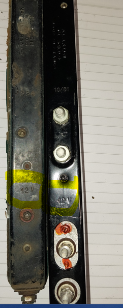
With no evidence of power going to the top two terminals (?) it was assumed that they were either earths or mounting points. After carefully dismantling the flashing unit from the housing, it became evident that they were mounting bolts.

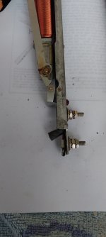
Mounting the flasher unit into a vice, power was connected to each of the two bottom terminals separately. As stated before, one operated the bulb and the second the solenoid. Both circuits worked perfectly independently. The two terminals were then configured into a parallel configuration with small jump wires. With power reapplied, the arm raised and the bulb glowed. The arm did however, raise slowly and not to its full height. From long ago foggy memory, I recalled this happening on other 203’s I’d seen.

As a precautionary measure, the semaphores will be fitted with solid-state flashing LED’s These will negate the need to run additional wiring and a flasher can unit etc.. At any time into the future, standard non-flashing Festoon bulbs can be re-installed. For some reason and I am assuming that the LED draws less current than the festoon bulb, thus supplying more current to the solenoid, which in turn enabled it to open to full height. (?)

bulb and Arm.png


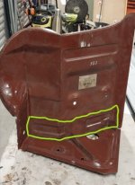
To insert the new units into the existing housing, some slight modifications will need to be made.

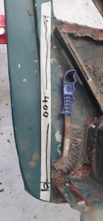
The power source connections are at the base of the units within the sedan versions and the Ute version, enter through the rear of the housing. This will be overcome by re-routing the wires within the base of the units.

The Ute units are more rectangular in shape as opposed to the slightly tapered sedan version.

tappered arms.jpg
housings.jpg


As are the internals of the units. This won’t be a problem as the arm recoil bush (Rubber grommet) can be trimmed to allow the arm to return to a lower position within the sedan housing.

arm and grommet.jpg


Click on the image to play video.

A little knowledge can be dangerous at times, but it paid off this morning.

Cheers,

Dano
 

Attachments

  • rebound grommet.jpg
    rebound grommet.jpg
    633.9 KB · Views: 96
Dan, refer to my recent email on this subject. The second terminal is a later modification to route the bulb through the dash tell-tale. Also, check that all joints are free and lubricated and that the earthing bolts are free of corrosion. Rule number one when dealing with electrickery is to check the earth first!
 
Put Belle up on the new rotisserie today.

Rotisserie.jpg


A bit of dicking around, but it is perfectly balanced. It will stop anywhere, throughout a 360-degree rotation. Couldn’t make it for the price.

A couple of stills of what was found.

subframe.jpg
front crossmenber.jpg

Chassis rail right.jpg


The replacement Peugeot Press panels will make the job a lot easier. Still a lot of work though.


index.php


The following link is a walk past from the back to front.


Cheers,


Dano
 

Attachments

  • 1680409553145.png
    1680409553145.png
    235.7 KB · Views: 88
This gem arrived in the mail today.

1680516329345.png
1680516627637.png


Thanks to Alastair Inglis and Geoff Higson both members of Club Peugeot UK, for making this happen.

It is a RHD gear lever steering column cover. A very rare item!

The seller in France, was reluctant to send it outside of France. With Alastair’s help and Geoff’s trip to France, it has found its way down under.

The worldwide Peugeot 203 fellowship is alive and well.

Cheers,

Dano
 
What a great find. If a I remember correctly, Gordon Miller once had some cast in aluminium alloy. That was many years ago and they were rare back then.
 
Spent the morning measuring and tri-angulating every reference point that could found on the floorpan of Belle.

cross referencing.jpg


The replacement floorpans are very close to shape. However the thinking is, Pascal must make them a little oversize to allow for fitting and trimming into the chassis of different vehicles. The downside is, there are no in floor mounting bolts or drain holes that can be used as reference points, so every bolt, bolt hole and drain hole in the existing floors, were measured and cross referenced in preparation for transposing to the new floor sections. This was followed by doing the same for the front bumper box channel, radiator mounting points, battery trays and backing panels. Sill and door openings were also done.

To repair the front chassis rails and removal of the bumper box section, will require supporting the chassis where the engine crossmember is mounted and removal of the front half of the rotisserie.

These NOS panels have been acquired over time.

new panels - battery.jpg


The battery tray and backing panel (Righthand side) will be used as a guide to fabricate the bottom quarter (As outlined) then that will be grafted into to the new battery tray section and lefthand side existing backing panel.

The complete cross section will save a lot fabrication work.

cross member.jpg


Where to start first is the question. That will take a few more cups of tea and periods of staring at it. Now matter where it starts, it will require the removal of many previously patched and bogged sections.
 

Attachments

  • front panel.jpg
    front panel.jpg
    49.2 KB · Views: 96
  • Screenshot 2023-04-07 162540.jpg
    Screenshot 2023-04-07 162540.jpg
    34 KB · Views: 92
obviously if the bottom was ground off flush you could offer up the pressings to trace and punch the locations?
rather than just assuming a) you have this and b) it's no help without triangulations, pls find att.:
Peugeot203soubassement copy.jpg

and lemme know if you can use it as a 1MB pdf
 
Last edited:
Appears the backseat floor met the prop shaft at some stage? seems rather severe ...
 
- that said, my 56 wagon had probably had it's leaves reversed more than once
bump stop.jpg
 
obviously if the bottom was ground off flush you could offer up the pressings to trace and punch the locations?
rather than just assuming a) you have this and b) it's no help without triangulations, pls find att.:
View attachment 219462
and lemme know if you can use it as a 1MB pdf
Hi Steve,

That will be a big help (PDF). Best part from what I can gather so far, is the measurements taken are the same as in the image?

What manual did you source the image from? I can't find it in any of the ones I have.

Will PM you my email address.

Cheers

Dano
 
Some more bling bits for the old girl. Period driving lights. Not French , but right era.
Thanks Scott, a good find at the swap meet.

1681527838346.png
 
Trial test patch for the right-side A Pillar was made this arvo.

First up the damaged area was taped up for marking out purposes.

Screenshot 2023-04-22 165812.jpg
Screenshot 2023-04-22 170114.jpg


Offcuts of 20mm hardwood were used to make the profiling bucks. An upper and bottom were shaped. The bottom one, incorporated the curve and incline of the front panel.

Screenshot 2023-04-22 170258.jpg
Screenshot 2023-04-22 170222.jpg


The top one was simply curved to act as clamp to secure the metal in place. All three pieces were screwed together.

Screenshot 2023-04-22 170450.jpg


Using an array of hammers, the metal was caressed into the profile of the bottom buck.

Screenshot 2023-04-22 170611.jpg


It appears to be the be a good fit. Next step is to cut out the rust and match the patch to the hole.

Screenshot 2023-04-22 170703.jpg
 
This is under the back corner of the bonnet? Why does that rust - sunroof drain ?
FWIW, that taping reminded me of an airframe restorers trick for getting a 3D template for complex compound curved sections using a tape that incorporated woven fibre, layers of it, applied crossply, so it held or returned to the shape after being peeled off ...
 
Very impressive work, Dan. Lessons well learnt from the 404!
 
Yeah, it is an interesting place for rust. The car doesn't have a sunroof and the panel is a single skin.

It appears to be the only rust in the car, above the floor line and sills.

The tape method is a handy tip, which was picked up from an old school panel beater who helped rebuild the lower windscreen and air dam channel panels on the 404. The method he used, was to apply layers of masking tape in opposite directions. His thinking was it won’t stretch. The tape is applied without stretching it tight, thus preventing the pull back effect of tape under tension. As Steven mentioned, the layers can be peeled off and laid out on the new metal for tracing etc.

The image below, is the damage to the left side which is similar to that on the right side.

Screenshot 2023-04-23 195302.jpg
 
Appears the backseat floor met the prop shaft at some stage? seems rather severe ...
1682332170037.png
1682332525856.png

Was a little concerned about the creased floor (left image), until the image on the right was spotted on the web.
Looks like it has the same bend webbing on the leading edge near the seat brace.
 
This slightly enlarged schematic should make it easy to copy and create new wiring looms for Belle.
It has been printed in A1 format, 841 x 594 mm. The numbers etc are extremely clear. No distortion from the original PDF, which came out of the owner's glovebox handbook.
View attachment 217962
Dan, if you are going to make your own loom i have a box of s/h numbered peugeot ends if you would like them .
it is pretty straight forward to make your own loom using an original pegged on a board(may be able help with an original loom )
black cloth tape on fleabay is good the wrap the loom
 
looking at floor photos from now on, but you may find this comforting too;
-10erw1.jpg
 
On the weekend, it was time to restarted work on Belle again.

In preparation to remove and replace the floor panels, sills and the ‘B’ pillar for repairs, a rear door space template was produced. This panel will ensure that the Sills and ‘B’ pillar go back exactly into place.

20240309_111040.jpg


As the pillars will be cut out, 25mm square section tubes were cut to length to brace the roof into place. The tube will be attached to the internal roof re-enforcing panel and the transmission tunnel.

20240309_112007.jpg
20240309_112348.jpg

Every thing is measured twice if not more and written onto the braces or panels.

This is where things came to stop. Connected the welder etc, only to find the cylinder gauge indicated it was empty. Mmmm!

Only one pillar needs reapairing, although both will be replaced. A NOS pillar was found sometime ago for the other side. Having a clean/new pillar will make it easier to create patch panel sections.

B pillar clip.png


The obvious rust throughout the car will be removed/repaired before the shell and doors etc. are sandblasted. Last time it was blasted first, but the protective covering caused more issues than wanted.
 
Top