Project Belle'

Good times in the shed this morning . Made even better, when Scott (Demannu) dropped in to lend a hand.

Screenshot 2023-02-25 153020.jpg


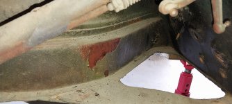
After a couple of hours, we had all remaining mechanicals out. The motor wasn't in the car, when it was purchased so that save time.

Screenshot 2023-02-25 153155.jpg
The new Supervisor was keeping a close eye on everything.

Getting the fuel tank out was a bit dicky, as it had been glued/sikaflexed in place. It also had a covering of epoxy all over it.

fuel tank out.jpg
Tank out.jpg
grill and headlight out.jpg
Headlights and grille removed.

cross member.jpg
.
Discs.jpg

The disc brake set-ups are heading to Melbourne......

Gearbos and torque tube..jpg
Would appreciate it, if someone can tell me why the speedo cable wont come out. The locking screw set up has been totally removed and the cable head moves freely in the box housing .Resonable force has been applied when trying to pull it out.


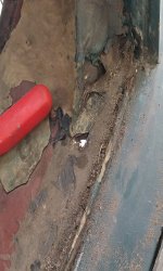
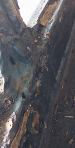
As expected rust and some doggy repairs are starting to become evident. Oh well, it is 68 years old. Definietely no complaints though.


Cheers,

Dano
 
Great to see this thread up and running, Dano. Hopefully, you'll have less rust to cope with this time around.
 
i think pete had trouble with speedo cable - i'll ask.
Demannu vocalises anythinks about a DW10CTED4 application, i wanna know.
 
Front and rear screens out. Luckily, I remember the screens go in and out from inside the cabin. You'd be pulling your out, if you tried to take them out from outside... Just not possible!

front screen.jpg
front screen out.jpg

back screen.jpg
 
More steps forward…

It’s almost a shell of itself.

shell.jpg

The dash, hood lining and wiring is all that is left to be removed.

Remaking a new loom will be interesting? There is a mixture of old and new wires running everywhere. Heaps are just wires with no terminals or connected to anything.

Both chassis rails are rust free.
front left chassis rail outside.jpg


The two battery holder trays (2 x 6 Volt in series), will need remedial work.
inside front right gurad.jpg
inside front right guard.jpg


The floor section under the right chassis rail, will need repair.

front right rail top.jpg


Left hand side is good.
inside left rail.jpg


The guard bolts/screws on both sides had to be drilled out. They were covered with bog! Nothing was going to budge them. The guards,where they wrap around the A pillar at the bottom are rust damaged and will need to be patch. There are spare guards stored under the house, so the best ones will be chosen.

left front door guard bolts.jpg


The sills have been patched previously and are somewhat questionable.
repaired left rail.jpg


The rust doesn't look too bad (?), but I'll wait to see what it really looks like, after a full body sandblast.

Cheers,

Dano
 

Attachments

  • right boot.jpg
    right boot.jpg
    647.5 KB · Views: 105
  • inside right rail.jpg
    inside right rail.jpg
    938.4 KB · Views: 107
Hi Dan. Not sure if I mentioned this to you in the past. If you want to remove the headlining in one piece it can be lifted off the barbed strip with a paint scraper. Just go carefully around the edges. The old one could be useful as a pattern.

Tony
 
Hi Dan. Not sure if I mentioned this to you in the past. If you want to remove the headlining in one piece it can be lifted off the barbed strip with a paint scraper. Just go carefully around the edges. The old one could be useful as a pattern.

Tony
No Tony, you hadnt't but I will certainly take note. A good hint.
Dan
 
Spent the morning, organizing and cataloguing the spare parts purchased to undertake the task. A lot less bits required, compared to the 404 restoration.
A few more parts to source, mainly trim and wiring stuff.
1677917785816.png
 
The hood lining was removed today. Interesting to see how things were done in the past. The hoops are flat spring steel (?). Due to the lack of a pinch seam around the doors, the vinyl is nailed to what looks like twisted cane, that is also nailed into a channel that runs around the door frames.
hood lining one.png
stripped lining.jpg


rolled cane.png
Not sure if that material is still available these days? If not, I think I’ll use strips of either MDF or ply. Cutting the curved profiles could be a pain.

barb strip.png
The lining is tensioned by a spiked rail attached to the roof frame.

Everything is held into place with what looks like twisted Blue Tacks.

The hood lining is seven individual sections all stitched together. One piece would be so much easier to reproduce.

The dash wiring (Now that is a loose description), is a nightmare! Lots of non-standard switches and a temperature gauge. The gauge was held into place with hose clamp. Nothing is tapped together and no form of colour coding or numbering to help identify what runs where. In some cases, different colour wires have been added together / extended in line.

wiring mess.png
one way of mounting an instrument.png


Not surprised that there is rust in and around the bottom of the A and B Pillars.

Rust 2.png
rust left A pillar.png


It is nowhere near as bad as was the 404, so that is a good thing.
 

Attachments

  • Rust 1.png
    Rust 1.png
    279.1 KB · Views: 97
Last edited:
Dano , being aware of your desire for originality , no doubt you will ditch the temperature gauge held in with the hose clamp.I was surprised to see a gauge in a 203 coming up for auction here in Victoria , which has the large back window but is not a C model . This gauge appears to be combined with the oil warning light as was the case in 403 . It seems that the early large back window 203 had this as standard ? In any event , perhaps you could get a temperature warning light by incorporating a sender on the engine to activate the oil low pressure light when overheating , This would give a better result than was the case with , for example , FJ Holden with an overheating warning light ( the so called idiot light ) which I had a problem with about 60 years ago when the globe had blown and there was no means by which you could see when driving that it was still operative. If the light comes on with low oil pressure or overheating , the gauge may not be required.
 
The temperature gauge was only fitted to the 203 (Lux) from 1959. I don't like to take wind out of your sails but you may not know that most modern cars are fitted with a temperature idiot light in the form of a gauge. The gauge needle is electronically dampened from cold until it stops at the mid point. Any travel beyond that point is just triggered by a switch like an idiot light. By the time the gauge reads hot it's too late. Great money saver - my old Lexus IS 250 had a real gauge - my new IS350 has the usual Toyota one!
 
The temperature gauge was only fitted to the 203 (Lux) from 1959. I don't like to take wind out of your sails but you may not know that most modern cars are fitted with a temperature idiot light in the form of a gauge. The gauge needle is electronically dampened from cold until it stops at the mid point. Any travel beyond that point is just triggered by a switch like an idiot light. By the time the gauge reads hot it's too late. Great money saver - my old Lexus IS 250 had a real gauge - my new IS350 has the usual Toyota one!

This might explain why my Landcruiser temperature gauge does not move beyond about the half-way point when I'm pulling something heavy up a hill on a hot day, whereas the new Redarc gauge changes quickly, and has been known to reach 117C :eek:
 
This slightly enlarged schematic should make it easy to copy and create new wiring looms for Belle.
It has been printed in A1 format, 841 x 594 mm. The numbers etc are extremely clear. No distortion from the original PDF, which came out of the owner's glovebox handbook.
1678262005780.png
 
Tracked, tagged and removed the wiring looms today. It was made easier, using the continuity buzzer function on the multimeter. As suspected, there were a few circuits that were duplicated and the original wires still left in place. Using the enlarged wiring schematic made it easier to follow. The car had, had a set of flashing indicators grafted into the wiring at some stage. It was a little rough and ready installition . Some wires had no terminals attached, just stripped wire ends wound round the terminal posts.

labelled 2.png
labelled wires 1.png


I am sure that the old girl would have been blowing fuses on a regular basis with frayed wires like this, still being used for the rear tail lights.

frayed wire.png


The indicator (semaphore arms) wiring is a little confusing. The schematic being used, shows a white wire running between the indicators that have 2 terminals. The white wire then goes to the indicator light of the dashboard (Highlighted in image below) However there is no white wire in the loom from the car. The semaphores from the car, only have one terminal. Another owner's manual the 6th Edition, shows the configuration as per the looms in the car (Image on rihght below). Has anyone else come across this mystery and solved it?

2 schematics.png


Ages ago, I purchased a set of Ute semaphores, hoping to use the internals in the carcasses of the sedan semaphores. After an inspection today, it showed the Ute semaphores have two terminals. Are they of any use to me? Can they be modified or do I have to find a set of single terminal semaphores. The existing ones are ugly, but repairable I guess? Both sets are Klaxton brand.

inside semaphores.png
12 volt.png
Both are 12V units.

Did a little digging around under all the fibreglass and bog along the rear edge of the boot. It revealed some ugliness which was expected. Whoever did the repair work prior to the last owner, subscribed to the principle of cover everything under thick layers of bog so no one can see the rust damage. Oh well, it was expected…

rust 1.png
rust 2.png
I think there is suppose to be metal in there!


She is now a completely bare shell. The repair journey starts soon.

shell.png
 
Nice Work Dano, great to see progress.

404 running well? No more water pump leaks?
 
Top