
You are using an out of date browser. It may not display this or other websites correctly.
You should upgrade or use an alternative browser.
You should upgrade or use an alternative browser.
My R12 POS Arrived!
- Thread starter Bowie
- Start date
Could you print the plastic part with a 3d printer?
Yes I reckon that could be done quite easily fro someone with the printer and the software to go with it.
Or
If you have the patience you could probably make one from a lump of plastic.
GOOD NEWS EVERYBODY!
I found where the smoke came from.
View attachment 79174
You are looking at the underside the light arm in an early combined unit. That copper plate came loose, and that spring was being dragged around the terminal(s) reserved for the copper plate. HOW RUDE!
This is great though at it means this indeed was where the smoke came from. Note the orange burn marks and melted housing directly under the spring.
When I took it apart I was very confused. the copper plate, which should sit like this,
View attachment 79175
Was found at the complete other end!
View attachment 79182
Look at him with his arms out reaching for another circuit to short! What a sneaky sod! I'd hate to think how long he was apart like that. There is enough dirt and geese in there that I'd be confident it would start a fire if left... :S
It's a pretty fun little unit actually, but lets back up a bit and I'll show you how to get into it.
First get a dremmel and grind out the rivets. Oh I got a dremmel for Christmas. They are great! I managed to not destroy the housing and I think I'll be able to take it to my friendly bolt store and with a series of spacers install a replacement that will allow to me mount it back correctly!
View attachment 79186
Then bend the terminals 90 degrees do you can slide the ends out of them. Lastly there are two boring clips on the other end that pooped of easily enough, Didn't bother to show that here.
View attachment 79188
View attachment 79187
From here you can gaze upon the boring blinker side, which is really nothing but a case. The circuits on the outside seem to control the indicator, well report it's position to the switch.
View attachment 79185
Turning the lights on, actually moves a small arm on the lever that pushes on a plate within the housing, When its it's in configuration it looks like this;
View attachment 79180
The high beam flashing circuit (pushing the arm in) is controlled but the cap expanding into the sprung lever, Shown at the bottom of the image. That bar simply gets pushed into the terminal
View attachment 79179
The high beam switching circuit.. well I'm not exactly sure. There is a sliding plastic piece that moves between to the left and right position but has no contacts and connects not a thing. I have a feeling there were small springs that provided tension on the leaver and returned it into position. The circuit is control by the plate what failed above on mine. You can also clearly see the wear on the terminals from the copper plate traveling previous.
View attachment 79181
So I think I'll spray a lot of WD40 in there and clean it out as best I can. Apply a little more grease to the moving components, and think carefully about how the high beam circuit was supposed to be support by some small springs, and just how they connected.
This was the part that failed a pink slip actually. The sloppy lever was not welcomed by the mechanic.
Someone take theirs apart so I can see which bits I'm missing
I'm glad I confirmed this is where the fire came from, I'm feeling a little easier about the wires under the dash now.
Bonus other pics of the arm below.
View attachment 79184
View attachment 79183
View attachment 79178
View attachment 79177
View attachment 79176
View attachment 79173
I finally dismantled an old style R12 light combination switch tonight. It had the floppy arm problem.
In pics 3,8,9 & 10 you can see where the plastic locating part is broken and the broken off bits have fell out. There are no electrical components to this part, all this part does is locate the head light switch in the correct place.
When these switches are operating correctly you will find that it is easy to move the switch from the off position to the low beam position and back to the off position. When you move the to the high beam position you will find it takes a little more pressure on the arm to make this happen. Now when you move between the low and high beam positions you will find it easy to move the arm. When you want to turn off the headlights going from the low beam to off position you will find that you will need that extra pressure again. This is all that little plastic part does.
The little switch plate that you found dislodged as show in pic 3 and should be as shown in pic 16 switches on the headlights and also does the low/high beam function.
These combination switches also have a unique function for flashing the head lights, when the park lights are off the high beam will flash and when the park lights are on the low beam will flash.
When I was going through my collection of headlight combination switches tonight I found three of the old type, one with the floppy are decease. The other two seem to function mechanically as they should but seem to be missing some wires. You are quite welcome to these combination switches for the price of postage as I doubt I will ever need them as I have found that I have plenty of the newer type. PM me your address and I will post them out to you if you want them.
Last edited:
REN TIN TIN said:...$93 and then forget about it for another 40 years.
Cheers
Ren
Well there is that too. A bit of perspective is not a bad thing
And Col, PM incoming. That would be a great help
Well I had that free afternoon to change that steering disc, flex, dampener over.. You know the one. sits at the end of the column before the steering rack joins into a universal joint
Well I thought, perhaps I can cut away at the rivets to save me taking the entire rack out. The Haynes warns me I could easily bugger it up :S
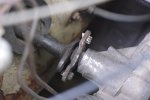
Well I reckon I may just have to go ahead and remove the rack to be able to fix the mess I made for myself.
There was no easy way to point the Dremal in a way to cut the head of cleanly, so I just hacked away at the base getting nowhere... giving up I cut through the old disc and tried to tap them out.. That was never going to work.
So.. removing the steering rack :S
Also... I guess the rubber disc acts as a kid of dampener on the steering wheel? muffling the road vibrations and smoothing out the action in the cabin. What does it feel like mounted directly?
Well I thought, perhaps I can cut away at the rivets to save me taking the entire rack out. The Haynes warns me I could easily bugger it up :S

Well I reckon I may just have to go ahead and remove the rack to be able to fix the mess I made for myself.

There was no easy way to point the Dremal in a way to cut the head of cleanly, so I just hacked away at the base getting nowhere... giving up I cut through the old disc and tried to tap them out.. That was never going to work.

So.. removing the steering rack :S
Also... I guess the rubber disc acts as a kid of dampener on the steering wheel? muffling the road vibrations and smoothing out the action in the cabin. What does it feel like mounted directly?
Well I had that free afternoon to change that steering disc, flex, dampener over.. You know the one. sits at the end of the column before the steering rack joins into a universal joint
View attachment 80073
Well I reckon I may just have to go ahead and remove the rack to be able to fix the mess I made for myself.
Also... I guess the rubber disc acts as a kid of dampener on the steering wheel? muffling the road vibrations and smoothing out the action in the cabin. What does it feel like mounted directly?
I would suggest that you don't go there. I think that that flexor is designed to tear in a heavy impact to prevent the steering wheel column coming right back at you.*
I know that Ken, formerly of Caravelle can get them. He thinks they are the same as Pug units.
*I could be completely mistaken, as I often am.
I seem to recall a Holden advert around the time of the HR showing a collapsing section of the steering column based on a concertina style coupling. It was heavily advertised on TV as a massive contribution to road safety. To my child's eye (at the time) it seemed like a significant engineering achievement. Big, robust and capable of rotating in normal use, but collapsing on impact.
Several years later I bought a Renault 4. As far I could determine that rubber coupling was the cheap, simple and elegant solution that
Renault had arrived at several years beforehand.
The flex coupling is effectively a (very low deflection angle) universal joint, it is not a safety coupling in the same way as the concertina type joint introduced on the HK Holden, and the flector is not designed to tear. The steering wheel would not be able to turn the wheels if the steering flector is removed.
But, couldn't you just bolt the end of the column directly to the rack, i.e turn the column 90 degrees and bolt it up?
Try it, and let us know how it goes.
It won't transmit any road vibration either ...really.
But, couldn't you just bolt the end of the column directly to the rack, i.e turn the column 90 degrees and bolt it up?
*ducks*
Yes, you can, and I have done it in a 504 rally car when I had a problem during a rally. But theoretically the column and the rack holes should be perfectly aligned as you rotate the steering wheel or you will generate some play. If you have the part, use it, no point trying to outsmart the manufacturer :wink2:
Cheers Thanos
So I managed to get a correct right angle attachment for my little spinny cutting machine of death (Dremel) and I thought if I cut as close to the housing as possible, I could pull the other end out with pliers.. I mean.. that's how rivets work right?
Anyway no dice (oh does anyone want to by a 3000 series Dremel, used for 30mins, then went and bought the proper one (4200) that supports the right angle attachment, This 3000 was a gift, no chance of refund. $60?)
... So only solution now is to rip out the steering column. Was actually straight forward. although I was STUPID! enough to undo bolts whilst it was on the grass, without a tarp catching everything. There will be 3 nut heads I'll discover in 12m time when I get around to mowing that lawn. :S
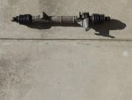
Aahhh now now there is nothing healthy about a tan R12 steering column. You be careful now.
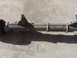
Serial number just for Simon
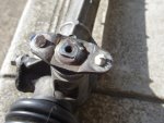
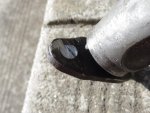
I thought I could cut these and rip whilst they were still in the car.. Nope. Now I'll add it to a vice somehow and drill through the middle. Screw you stupid little frayed rubber disc and screw you factory that riveted it initially. I really hope it saved you 0.5secconds in production because a mechanical luddite like myself is annoyed.
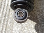
Happily bushel is not wrecked,
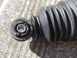
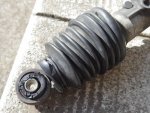
Oh the other side is though... Say I should put this back before anyone notices :S Do I dare go looking for these rubbers.. .. (BONUS! Boot is stating to give up too. Oh happy happy Joy Joy!)
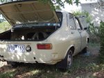
Still looks great without the bumpers. If you look closely you can probably see the tincy little LED plate light shiny up from the bottom. (and the tarp I layed down after loosing 90% of the bolt heads...) I doubt this will provide enough coverage, the colour it casts whilst on in the middle of the day might be enough to confuse the inspector Either way the real plan is a little more elegant. I'll be enlarging the licence plate holes and using 2 of these bullet styled lights as retainers
  BAM!
BAM!
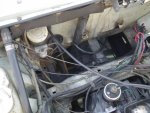
No huge amounts of rust! Yaaaaaaaaaaah
Perhaps I can mount it in the rear for Honda spec 4WS... #JOKES!
So I managed to get a correct right angle attachment for my little spinny cutting machine of death (Dremel) and I thought if I cut as close to the housing as possible, I could pull the other end out with pliers.. I mean.. that's how rivets work right?
Anyway no dice (oh does anyone want to by a 3000 series Dremel, used for 30mins, then went and bought the proper one (4200) that supports the right angle attachment, This 3000 was a gift, no chance of refund. $60?)
... So only solution now is to rip out the steering column. Was actually straight forward. although I was STUPID! enough to undo bolts whilst it was on the grass, without a tarp catching everything. There will be 3 nut heads I'll discover in 12m time when I get around to mowing that lawn. :S

Aahhh now now there is nothing healthy about a tan R12 steering column. You be careful now.

Serial number just for Simon


I thought I could cut these and rip whilst they were still in the car.. Nope. Now I'll add it to a vice somehow and drill through the middle. Screw you stupid little frayed rubber disc and screw you factory that riveted it initially. I really hope it saved you 0.5secconds in production because a mechanical luddite like myself is annoyed.

Happily bushel is not wrecked,


Oh the other side is though... Say I should put this back before anyone notices :S Do I dare go looking for these rubbers.. .. (BONUS! Boot is stating to give up too. Oh happy happy Joy Joy!)

Still looks great without the bumpers. If you look closely you can probably see the tincy little LED plate light shiny up from the bottom. (and the tarp I layed down after loosing 90% of the bolt heads...) I doubt this will provide enough coverage, the colour it casts whilst on in the middle of the day might be enough to confuse the inspector

No huge amounts of rust! Yaaaaaaaaaaah

Perhaps I can mount it in the rear for Honda spec 4WS... #JOKES!
Last edited:
Tell you what, that's all looking pretty good considering the age of the average R12. Great cars and good quality materials IMHO. Best not to work on them deep in the bush though. Mow it first! 
You can buy generic boots that will fit from Autopro and perhaps Super Cheap. They have a range of sizes at each end that can be cut to suit.
Ah good to know. No excuses to not replace them then. I note these boots had a rubber band around them.. A cable tie would be as good or do the ends needs to stretch and move a bit?
If the rubber band is serviceable use that. Cable ties can cut into the rubber a bit, particularly if there's any oil about. If you do use a cable tie use the widest band you can and tighten it as much as you need to not as much as you can.
Ex
Ex
Cable ties will work fine on securing the ends of the boot. Perhaps Ken at Creative Intentions in Melbourne (Mob. 0400566119)will have your end bushes. Quite often the anti rattle bush kit that goes into the end of the rack on the passenger side to support the shaft is worn. Not overly expensive, and certainly worth checking when you have gone so far.