I'm have no idea how the crack happened. I imagine a suspect crankshaft was ground down to much when the engine was rebuilt. it broke while I was cruising along doing about 37mph. I imagine it has been cracked for many years and took this long to fatigue through. My daughter told me two days previously the car didn't sound right, but I couldn't hear what she was talking about. She must have far better hearing than me!

You are using an out of date browser. It may not display this or other websites correctly.
You should upgrade or use an alternative browser.
You should upgrade or use an alternative browser.
ID19 gearboxes
- Thread starter DoubleChevron
- Start date
Have you measured how far the crank was ground from its original 48mm?
Sorry I cannot help with another crank, but I gave all my DS 19 engine bits to Roger before he passed. It was this engine that was subject of his engine rebuild thread!
Last edited:
Have you measured how far the grank was ground from its original 48mm?
Sorry I cannot help with another crank, but I gave all my DS 19 engine bits to Roger before he passed. It was this engine that was subject of his engine rebuild thread!
That's ok ... I will have one here, I just need to pull it out. The journal look machine shop fresh ..... er, apart from that big crack that is
 ... I'll run the calipers over them and see what we get. I measure 47.5 ... that should be nothing. Its a HUGE journal. I'd say this crankshaft had done a million miles and was just fatigued when re-used.
Agree 0.5 mm is nothing!! Out of interest, can you see where the crack first started? I just wondered whether it was right at the corner at the edge of the journal? It's so hard to believe it cracked!! Seeing is believing...
That's ok ... I will have one here, I just need to pull it out. The journal look machine shop fresh ..... er, apart from that big crack that is
Looking at the travel line of the crack I would be prone to suggest that the proper radius between the journal and the crank webb was not adhered to. A sharp corner at this point introduces stress focus. The proper radius spreads the stresses so that they do not concentrate at one point. Maybe the crank was reground by an inexperienced operator?
BTW shells come in .25mm undersize steps up to 1mm.
BTW shells come in .25mm undersize steps up to 1mm.
Looking at the travel line of the crack I would be prone to suggest that the proper radius between the journal and the crank webb was not adhered to. A sharp corner at this point introduces stress focus. The proper radius spreads the stresses so that they do not concentrate at one point. Maybe the crank was reground by an inexperienced operator?
BTW shells come in .25mm undersize steps up to 1mm.
Anything is possible. I'll see when I pull it out so I can measure all of the journals. Everywhere I tried I got 47.5 ... so it seemed round and level from what I can tel with a cheap crappy aldi micrometer
")
while I've been stuck working at home ... I figured making the car easier to assemble will save a huge amount of time (so many missing and incorrect fasteners on it!).
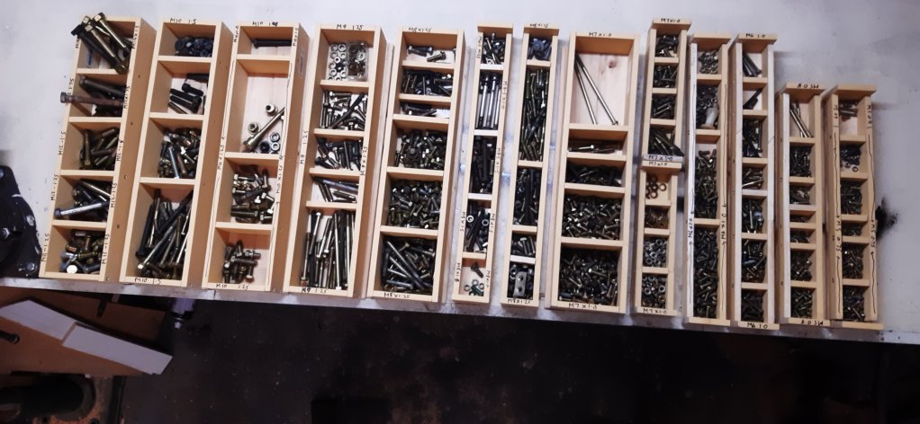
The "funnest" fasteners to find on the early stuff is all the missing and broken M5 x 0.75 ... especiallly where someone has forced M5 x 0.8 into the captive nuts. There seems to be M14 -> m5 there. with an odd range of thread pitches.
The "funnest" fasteners to find on the early stuff is all the missing and broken M5 x 0.75 ... especiallly where someone has forced M5 x 0.8 into the captive nuts. There seems to be M14 -> m5 there. with an odd range of thread pitches.
Attachments
Shane, if your daughter has an ear like that she has mechanical aptitude, so teach her all you can about mechanical matters. I know both your daughters are seriously smart.
And you are welcome to organise my fasteners any time.
Roger
And you are welcome to organise my fasteners any time.
Roger
Shane, if your daughter has an ear like that she has mechanical aptitude, so teach her all you can about mechanical matters. I know both your daughters are seriously smart.
Roger
I second that, bit of mechanical sympathy with even basic knowledge can save them plenty of $$$$ over a lifetime. I know my daughter saved cooking an engine on a car she was driving by being alert and switched on, back then the money she saved was was mine because she was in still studying.
while I've been stuck working at home ... I figured making the car easier to assemble will save a huge amount of time (so many missing and incorrect fasteners on it!).
The "funnest" fasteners to find on the early stuff is all the missing and broken M5 x 0.75 ... especiallly where someone has forced M5 x 0.8 into the captive nuts. There seems to be M14 -> m5 there. with an odd range of thread pitches.
I have mostly given up on M5 x 0.75 fasteners. I calculated that if you run an M5 x 0.8 tap through the captive nuts, you lose one thread every 12mm, so the average nut loses only a small amount of holding power. Where there is a long M5 x 0.75 stud, I run an M5 x 0.75 tap (available even here in the States) through a readily available M5 x 0.8 nut. Problem solved. I try to use stainless steel nuts so that I don't have to worry about the tap removing the plating from the nut threads...
Thanks for that - I had NO idea anyone had run a crownwheel and pinion backwards! Apparently it worked all right? "Interesting" character, Colin Chapman...
I guess it worked well enough for Lotus to sell quite a few Esprits with the Citroen transaxle. In the long run, however, it gave poor service. Not only is the coast side of the crown wheel less robust, but the thrust vectors of the helical gears added to, rather than offset, the crown wheel to pinion thrust. The Esprit became notorious for having CWP problems and eventually Lotus changed to a transaxle supplied by Renault. A few years ago, Harry Martens in the Netherlands actually started making mirror image CWP sets for the Lotus Esprit with the Citroen transaxle so that the transmission would at least be driving the pinion against the drive side of the crown wheel.....
Bloke by the name of Brabham got involved a bit too! They ran them with the CWP in reverse did they? That original Chapman work on Coopers must have been pretty early I guess? Fascinating stuff. I was looking at a Traction gearbox after overhaul a few months ago - some interesting design features...
No! They flipped the whole diff over so that the drive was still on the driving flank of the tooth but of course that made it turn in the opposite direction!
Yes, the traction gearbox was a brilliant design. Unfortunately it was much maligned by people that treated them badly, assembled them poorly and turned around to blame their misfortunes on anyone other than themselves. Human nature?
The elimination of just one multi tab locking washer gets rid of the only questionable feature. If only Loctite had been available in 1934!
well this has been fun ....

that was a huge amount of work.

does anyone know of an easy way to remove that oil pump. I've removed the clamping bolt, but don't want to force anything. THe motor didn't have a sparkplug on No4. so I can't turn it over. to get to the rod bolts. Amazingly when I removed a couple of shells, there was still a clean oil film between them and the crank

I might see I my grandfather can have a look at this crank for me. He'll know if its ok ( he's in his 90's now, so may have little interest in looking at it. we'll see ).
that was a huge amount of work.
does anyone know of an easy way to remove that oil pump. I've removed the clamping bolt, but don't want to force anything. THe motor didn't have a sparkplug on No4. so I can't turn it over. to get to the rod bolts. Amazingly when I removed a couple of shells, there was still a clean oil film between them and the crank
I might see I my grandfather can have a look at this crank for me. He'll know if its ok ( he's in his 90's now, so may have little interest in looking at it. we'll see ).
Looks reasonable. I remember when Roger Brundle said that those old strainers attached to the pump were only suitable for straining out Dogs and cats!
Have you removed the pinch bolt through the side of the block (and the oil pipe, of course)? If it still cannot be removed by pulling/wiggling, try removing the dizzy, then use a long drift against the drive gear to tap (or more likely bash) it out.
Indeed. That is why I added a full flow oil filter to my long stroke 61DS19. I am also in the process of adding one to my '54 11BL.Looks reasonable. I remember when Roger Brundle said that those old strainers attached to the pump were only suitable for straining out Dogs and cats!
Nicely doneIndeed. That is why I added a full flow oil filter to my long stroke 61DS19. I am also in the process of adding one to my '54 11BL. View attachment 121389

My father walked into the shed and looked at it .... and said, "the oil pump will be driven by the dizzie" ... followed it up and said "have you tried removing that retaining bolt" ..... I can always see the obvious when someone points it out to me
I'll try later and see what I have.The oil pump is driven by the cam shaft. The dizzie sit into the top of the oil pump shaft drive gear. Orientation of the drive slot which is offset from the centre line is important. Refer to the W/S manual.
Removing the retaining bolt on the side of the engine block allows the oil pump to be withdrawn from the block when the sump is removed. The pump should slide straight out once the main feed pipe to the galleries is removed. A couple of twists should see it come free easily.
Removing the retaining bolt on the side of the engine block allows the oil pump to be withdrawn from the block when the sump is removed. The pump should slide straight out once the main feed pipe to the galleries is removed. A couple of twists should see it come free easily.
Last edited by a moderator:
thanks all... Wel I'm glad tools aren't expnesive these days.... I've never struck a 46mm nut before on a Citroen! That oil pump is, er, "snug". There hasn't been a dizzie in the motor for years, so I'm guessing its stuck in place. I'll be able to get the crank out around it.
I also split my australian made sidchrome 12mm socket on the bearing shells.... and damaged another cheapo. They were certainly certainly weren't going to fall off
I also split my australian made sidchrome 12mm socket on the bearing shells.... and damaged another cheapo. They were certainly certainly weren't going to fall off
I have a Starwhille 6 point 12mm socket that is perfect for these con rod bolts. 12 point sockets tend to jump off and round out the corners of the hexagon. If you wish you may borrow it!thanks all... Wel I'm glad tools aren't expnesive these days.... I've never struck a 46mm nut before on a Citroen! That oil pump is, er, "snug". There hasn't been a dizzie in the motor for years, so I'm guessing its stuck in place. I'll be able to get the crank out around it.
I also split my australian made sidchrome 12mm socket on the bearing shells.... and damaged another cheapo. They were certainly certainly weren't going to fall off