2011 RCZ THP200 midlife makeover

good grief. here would be an overview of the rcz here.

every 20,000km ... change oil and filter.... even throw an air cleaner and fuel filter at it sometimes

13years later ... .@ 180,000kms change cambelt

keep changing oil and filter every 20,000kms.... maybe throw an air and fuel filter at it.

job done :)

Out of interest, why did it need a clutch at only 80,000kms ?
I wanted a lightened flywheel so it was a matter of course to replace the clutch at the same time. I have changed my engine oil every 5,000 kilometres, or less, on every car I have owned.

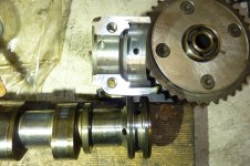
I took the cam cover off my Nissan Pulsar N14 SSS recently. I have owned it from brand new 1992. Currently on 145,000 klicks. Oil has been changed about 76 times now. The inside of the cam cover, cams, lifters etc were shining metal and alloy. Sparkling in fact. NOT ONE TARNISH OR STAIN. Engine compression is still at factory spec. When I drain the oil it comes out golden.
DSCN0333.jpg
 
207CC- did fitting a new clutch make any difference to the pedal height?

Was the cleaning of the MAF and air pressure sensors in response to ECU fault codes?

What is the recommended interval for replacing the fuel filter? (I haven't spotted mine yet!)
Check this out:

 
Loving this thread. Assume there’s no way to adjust (reduce) the pedal height on the RCZ (like the old Mi16 etc)?
 
Yeah, I never liked it. They don’t start to engage till at least half way up, so it’s wasted pedal travel. Way too high. Assume it’s not adjustable?
 
That's how it is, and I like it. The lower brake pedal is for heel/toe gear changes.

I installed a left foot rest plate, which brought my left foot a bit higher. I like clutch engagement closer from the floor. Just push harder and don't get a stiffie . . .
 
Thanks 207cc- I look forward to the day when I have nothing else to do than find the fuel filter.

I finally reached the stage where I had fitted the first replacement parts to the engine in my attempt at addressing the fault codes associated with valve timing and turbo boost – a 2nd hand exhaust Vanos unit and a new turbo boost solenoid. I removed both existing camshaft sprockets, and using degreaser and compressed air cleaned off excess oil in the existing inlet unit and the replacement exhaust unit. As well, of course, cleaning the camshaft ends. I reused the camshaft bolts and existing tensioner which has about 4mm of stroke left in the piston. I have found from previous experience with my DS5 petrol that reusing the camshaft bolts is not an immediate disaster (5 years and 20k km later the timing is still fine). I figure I may well be back working in this region anyway.

Fitting the turbo boost solenoid was only made possible by removing a chassis cross bar and disconnecting the lower engine mount link and levering the bottom of the engine away from the bulkhead. It was also a bit easier because the inlet manifold was still loose from the valve cleaning episode.

Reassembling the engine peripherals brought me back to the gunked-up intercooler. Soaking the intercooler in 4lt of kero did nothing to the black, solid gunk. I picked out bits of it and put them in Vegemite jars containing metho, turps and acetone respectively. No effect! I resorted to picking at it as best I could and thumping the unit on a block of wood. I doubt I made much improvement to air flow. I did spend some considerable time tidying up the cooling fins on the front of the unit, many of which bore the scars of impact damage.

The last bit to fit back on before I can drive the car and continue with the trouble-shooting was the front bumper. Now when I purchased the vehicle my main preoccupation was whether I was going to be mugged for the bank cheque I was carrying - the transaction was done at dusk in a Harvey Norman car park after all. Consequently I failed to notice that the front grille of the car had been stoved in- probably by a collision with a sparrow. This unit is euphemistically described by Peugeot as a stone guard (pt. no. 7422K1). And costs $717. And looking at the exploded diagram of what needs to be separated from the actual front bumper to replace this unit was not very reassuring. Bodywork is not really part of my skill set. Now I had come across YouTube videos of desperate owners replacing broken RCZ grilles with wire mesh. This was an idea I had warmed to- after all in 1962 I had replaced the anaemic grille of my mother’s Borgward Hansa 1100 with black wire mesh. I borrowed her car on occasions and in those days this sort of activity was considered necessary for trying to impress a young woman. So I duly ordered from eBay some diamond mesh whose photo looked ok but when it arrived looked more like fly wire - I had obviously missed the bit about the mesh being 3x6mm. Undeterred I figured I could at least use it as practice, and proceeded to attempt making cardboard patterns. This turned out to be non-trivial and dependent upon the extent of the damage to the grille. And there was the job of removing random bits of the grille still attached to the car, and modifying some horizontal ribs on either side that formerly supported horizontal chrome bars. This difficult process was not helped by remarks from my spouse like ‘it looks awful’ and ‘is this legal‘. I won’t really know it worked out until the front bumper is back on. Which has hit a slight snag. Sigh!

Both headlights show sun damage on the upper surface, and it would be highly desirable to polish them and recoat them with a UV protective film. I have previously used a product from Bunnings that worked well and was very reasonably priced. But I should do this before the bumper goes back on as it makes for an easier job.
 

Attachments

  • grille-inside.jpg
    grille-inside.jpg
    574.4 KB · Views: 27
  • grille-sides.jpg
    grille-sides.jpg
    397.5 KB · Views: 28
Both headlights show sun damage on the upper surface, and it would be highly desirable to polish them and recoat them with a UV protective film
I've tried a bunch of products over the years, and by far the best is CERAKOTE Ceramic Headlight Restoration Kit amazon.com.au/gp/product/B084RQKLV8/ - it's also very easy to apply compared to some of the others !
 
Dom the Trojan kit sounds very similar although I doubt it would last as well as the Cerakote product?

I was quite happy with the headlight job and proceeded to the next job in the queue which was to fill and bleed the cooling system – I had earlier installed new seals on the oil filter/cooler housing. It was easy to reach the bleed cap on the heater circuit near the bulkhead before the engine air ducting was installed. And the bleed screw on the thermostat was surprisingly accessible. I did note an extra bleed line running from the heater pipe area all the way around the front of the engine to the expansion tank. I also noted that leaving the car overnight with the front wheels up on the ramps was sufficient to empty the expansion tank of coolant!

The first mistake I made when fitting the front bumper was not having the fog lights already installed, and the second was that I should have connected all the hose and electrical connections before fitting the bumper. Those on the RHS are near impossible to do after the bumper is fitted. This entailed sitting the bumper on some boxes at the right height for fitting but a short distance in front of the car. When fitting the undertray I discovered that the front edge of both plastic wheel arch linings were cracked and broken – I think just from age rather than collision damage. I see part numbers for these- 7136KP and ..KQ but have doubts about their availability new. In the gloom of the garage the mesh grille didn’t look too bad but time will tell.

The final job was to reconnect the battery. However, the rubber pads on both key fobs were so damaged that I couldn’t be confident of any locking/unlocking procedures. That required transferring the blades and circuit boards to new cases – that cost all of $15.27 from China. I was pleased that my bench drill press, fitted with a suitable diameter blunt nail, did a nice job of pressing out (and in) the pins holding in the blades. The battery reconnection went fine and I removed the fuel pump fuse and turned the engine over to get a bit of oil circulating before attempting to start it. Started first time! I will attempt a few short runs around the neighborhood to see how it runs and finish the coolant bleeding.
 

Attachments

  • grille-1.jpg
    grille-1.jpg
    512 KB · Views: 23
After the initial promising start, it took four attempts to start it next time. I knew that the ECU might be expecting something in the way of resetting adaptations, but from previous experience I found that I would be less confused just letting it sort itself out over a few short drives. Admittedly, drives featuring lots of warnings like STOP, abs not working, and fog lamps not connected. Initially I got no warm air out of the heater and the temperature gauge was jumping about, but after three short trips and over a litre of added coolant things settled down and heat was produced. The only time it started first time was immediately after I had cleared the codes, otherwise it was three or four attempts, as though the car was making a point.
Which it was. Swapping the exhaust Vanos unit and re-timing the camshafts had not fixed the timing problem. In fact it was worse. The initial P000B (exhaust camshaft dephaser-linked control fault - intermittent) was generated after a 200km drive home from where I bought it. Now I could get many more codes after just driving down to the shops. And they were permanent. The codes generated (although not all occurring at the same time) were:

P000A: Inlet camshaft dephaser: linked control fault. The initial P000B (exhaust) came back but as an intermittent fault

P0012: Inlet camshaft dephasing-linked control fault

P0016: Synchronisation: lack of coherence between the engine speed sensor and inlet camshaft.

P0017: Synchronisation: lack of coherence between the engine speed sensor and exhaust camshaft sensor. Permanent.

When I checked the service records I saw that the P000B code was found at a service in mid-2022, when it needed 2.5 lts of oil added to it. At that time it was dealt with by fixing the oil leaks and changing the oil.

So I did what I should have done before changing anything- try to get some live data. My Launch reader can display reference and actual values for the camshafts although the graphic displays are primitive. However, my first attempt showed that the values were unchanging- for the inlet camshaft the actual and reference values were 14 degrees, and 2 degrees for the exhaust camshaft. I eventually realised that I could get some real data immediately after clearing the codes and before the ECU stepped in to protect the car. Which it did after about 300 readings.

The exhaust camshaft readings looked ok? (it helped that the scales for the two variables were the same) although there was a bit of a lag. The inlet results were puzzling, not helped by the different scales on the y-axis. The flat lines at the end were basically the same value but shifted on the display. Maybe Diagbox could do a better job if I went to the trouble of setting it up? But what looked odd was that the actual value did not follow the same pattern as the reference value.
 

Attachments

  • exhaust-1.png
    exhaust-1.png
    99.8 KB · Views: 16
  • inlet-1.png
    inlet-1.png
    93 KB · Views: 16
I thought that my next diagnostic step should be to check that my dodgy timing job was holding up and to replace the solenoid control valve for the inlet camshaft. I had a spare from a N13 BMW engine that looked very similar but that had 3 gauze filters instead of just the one on the RCZ. While I was at it I also replaced the camshaft tensioner with the longer one mentioned in MINI Service bulletin SI M110207 of May 2012. The one I bought has a total working length under the washer of 81mm, which leaves me 9.5mm of extension left out of the 24.4mm working range of the new tensioner. The cam timing was fine but I left the flywheel locking tool and camshaft clamps in place while I changed the tensioners as I wasn’t certain if something might move on me. Nothing moved, but next day it occurred to me that it might be worth checking the timing after rotating the engine a few turns. After the first few turns the camshafts were noticeably retarded- the inlet more so! So I rotated it again and this time the camshafts were slightly advanced! After the third lot of rotations the timing was perfect. I stopped while I was ahead and went inside and had a lie down. What was that all about?

The fault codes have not gone away. To date the inlet camshaft fault codes dominate- 23 times compared with 7 for the exhaust. Swapping cam sensors and the inlet solenoid did not make any obvious differences and I don’t think replacing the exhaust camshaft dephaser did either. I did have a DIAGBOX session with it clearing the codes and resetting adaptations, but at the point where it told me to take the car out and thrash it before returning it to the customer I ran into trouble. At 6000 rpm I had a drastic misfire and barely made it home- P1336 and P1337 (cyl. 1). On Friday I drove the car gently 17km into town and it did not misfire. On the return trip, after clearing the usual camshaft timing codes, it did not record anymore. This is a new development. I attach the latest plots for the inlet and exhaust camshaft, together with the options available on my Launch scan tool that I only recently discovered. I don’t think I would be game to go anywhere near them, but it does indicate to me that there is quite a bit of programming associated with the behaviour of the dephasers. I live in hope that mine have settled down. And the cause of the misfire will hopefully be a separate issue.
 

Attachments

  • Apr26 IN-1.png
    Apr26 IN-1.png
    103.5 KB · Views: 11
  • Apr26 EX-3.png
    Apr26 EX-3.png
    109.9 KB · Views: 12
  • options.png
    options.png
    104.4 KB · Views: 12
Even though I have nothing useful to contribute, please keep posting the story @gwest , this thread is fascinating 😎
 
Thank you Nom, I shall try to persevere.

I am beginning to think that my camshaft timing problems may have some systemic cause. There are disturbing instances on the internet where owners have renewed every likely component but still been left with dephaser malfeasance. Admittedly, in the Mini world some have found salvation through an ECU update. I’m not sure if there is a software update solution available to PSA tragics?

I see that my codes P000A and P000B are referred to as ‘slow response’. My exhaust dephaser (a replacement ex-BMW unit) is very slow to increase, and my inlet (original) slow to decrease (figs in previous post)

I also saw that: “P0016 sets when the ECM detects 8 of the last 10 cam pulses occur during the incorrect crankshaft position. P0017 sets when the ECM detects 25 out of the last 35 cam revolutions occur with 2 cam sensor pulses outside the CKP window”. Lately P0012 is more common and it seems to be associated with the inlet cam being retarded. Although the camshaft timing in the locked positions is correct, maybe the delayed response is interpreted as it being retarded?

Given that oil pressure is what motivates the dephasers it was convenient that I could record oil pressure on my code reader. It’s a nice feature of these engines with a controlled oil pump. I thought the actual pressure compared with the reference value looked ok? The oil pressure specs (in bar) I have for this engine are: 1000 rpm: 1.8, 2000: 2.0, 3000:2.6, 4000: 3.5. All +/- 0.3 bar.

Admittedly, it’s the actual pressure inside the dephasers that matters, and this is the reason many people replace the two sealing rings at the ends of the camshafts. It seems it doesn’t always fix it.
 

Attachments

  • Apr25 oil pressure.png
    Apr25 oil pressure.png
    91.3 KB · Views: 5
After another recent return trip from town in which there was no EML or beeps warning me to get the engine repaired, it finally dawned on me that the fault codes are being generated at startup, when the engine is cold!

My first thoughts were about the oil pump, but the plot shown in the previous post was taken fairly early in the sequence when the engine would have been cold. I attach a second plot taken earlier on that trip that shows much the same behaviour.

Next in line are the solenoids, but these have been cleaned and swapped around to the extent that I don’t hold out much hope of them being the culprits. And this is not a new problem- the previous owner would have known about it for several years and the solenoids are the prime suspects.

Something I only learnt recently from the MINI world is that there are removable one-way valves (pt. no. 023522) after the solenoids, whose role is to retain oil in the dephasers. Checking them can’t hurt but again I’m not hopeful. But of course the one on the intake side will be the more inaccessible.

And there are the two metallic seals at the dephaser end of the camshafts that my Haynes manual advises to replace with PTFE ones (pt. 080739). I have not had to touch these in previous engines I have worked on but who knows if it might help with this one? I know that PTFE seals are fitted dry but in the case of crankshaft seals they require an unusual sequence of engine rotations and then rest as part of the fitting sequence. I have no idea if this applies to the camshaft seals.

Then finally there are the dephasers, whose workings are only apparent from one video I found on YouTube-
.

The manufacturers obviously don’t intend owners to open them up as the recessed screws are not in the normal torx size sequence. And they appear to have a big spring in them anyway that could well prove fatal! At the moment I have a spare used intake dephaser soaking in kerosene in my ultrasonic cleaner thinking that maybe it’s worth giving it a go in case the existing one is a bit clogged up?
 

Attachments

  • Apr25 oil pressure engine cold.png
    Apr25 oil pressure engine cold.png
    91.7 KB · Views: 3
  • camshaft seal.jpg
    camshaft seal.jpg
    1.9 KB · Views: 4
There is a brief déphaseur comment here with a cross section. Google etc can translate. It comes from a discussion of the EP6DT.
 

Attachments

  • dephaseur.pdf
    62.4 KB · Views: 5
Thank you seasink- that was very helpful and I think I can finally begin to understand how it works. I attach a translation. So there are four sets of chambers with opposing sides supplied by the two outlets from the control solenoid. The four holes in the face of the dephaser (k in the diagram) get their oil from corresponding holes in the opposing end of the camshaft, while the other chamber (p) appears to get its oil supply through a central chamber where the main retaining bolt goes. The function of the coil spring is then presumably just to bring the dephaser back to the lock position after engine shutdown? I’m guessing that it is the four holes and chambers k that advance the timing, and the central supply (p) that retards it? So maybe wear in the two camshaft seals might be reflected in a slowness to advance the timing? It is not clear to me what might cause a slowness to retard.
It prompted me to dig out some leftover parts and have a closer look.
 

Attachments

  • dephaser.pdf
    163.6 KB · Views: 2
  • camshaft oil supply.jpg
    camshaft oil supply.jpg
    425.6 KB · Views: 3
Top