Resurrecting a Goddess.......Twice

Wow, that is incredible work on the exploded spagetti monster faulksy !
This sort of thing requires incredible patience and perseverence.

I'm still amazed by how the fire evaporated the roof..

Nice to meet you at Autoclassico on Sunday by the way.

Thanks again for these posts.
Ramon
 
The wiring was certainly fun to do. I've also got to make a new EFI wiring loom but that is far more straight forward as the wires don't branch off and go to multiple places. The loom is all done and installed, with a bit of luck I won't need relays for the headlights as I'll be remaking the front looms too at some point. I'll put some pics up soon of the finished setup. In the meantime

Episode 13: Off With Her Head!

Despite new wiring looms and a new battery the engine flatly refused to start. My efforts to get it going weren't being aided by an increasing sick sounding starter motor either. Turning the key caused the fuel pump to whir into life which indicated the ECU was probably ok so I decided to go spark hunting. First port of call was to remove no. 1 spark plug as it's by far the easiest to get to on a DX3 engine. It wasn't a pretty sight.....

48595986961_59d4dcc570.jpg


Looking down into the cylinder revealed a much worse problem. There was water sitting on top of the piston. The starter switch melted and shorted out during the fire which caused the stater to crank continuously for 20min. My though was that water had been pulled in through the throttle body and into the cylinders. I could have just pulled the plugs and cranked the engine but I wanted to check there was no damage internally so made the slightly ominous decision to pull the head. The bolts put up a fight but eventually all of them came loose. I'd love to have been in the design room the day someone realised the only way to remove the head bolt closes to the firewall was to cut a hole in the firewall to pass the socket down through. There's a rubber plug under the insulation in behind the dashboard. With the rocker shafts removed it was looking a bit sad.

48595987081_311c8eb557_z.jpg


The good news was that the cylinders were in perfect nick if a bit black and oily. There was only a teaspoon of water in cylinder 1 which must have come from the spark plug tube. Pulling the cam followings revealed there was no wear at all so I'm wondering if this engine was rebuilt at some point in its life.

48413494012_0f115fda4e_c.jpg


Having the head out of the way does give great access to some of the more hidden ancillaries such as the aux air valve and slow idle device. Seeing as I now had to wait a few weeks for new gaskets to arrive I figured it couldn't hurt to service them as neither seemed to be working properly before.
 
Last edited:
Bloody hell michael - you show no fear!

Very impressed mate - you will be teaching the lot of us soon

Just remember to ask if you need a part - I had a spare gasket set sitting on the shelf ion the man cave - we have quite a good parts store now

This car is going to be great when it is done - given everything is being checked over it should be a very reliable driver

Keep up the good work
 
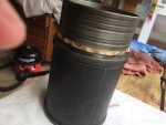
With the head off, it's standard practice to clamp the cylinder liners in place to stop them moving. If they lift (due to crank/ piston movement) or rotate slightly, then you will tear the ridiculously delicate paper "O" rings that they sit on and which separate the coolant from the oil beneath.....

I can see your engine is out. (That makes it a little easier). For peace of mind you may want to think about taking out those liners and replacing those gaskets. Though that means pulling off the crank and removing the pistons and con rods. full engine strip effectively (sorry!).

Yo might be lucky with your liners if you clamp them asap, but if you just decide to risk it and go with it, you may find you get coolant in your oil only when you rebuild and run it.

paper gasket on sleeve copy.jpg

IMG_5758 copy.jpg
 
I did read that in the manual. It was pretty late by the time we lifted the head off and search around the shed turned up no suitable bolts. The car is on blocks at the end of a driveway and can't be moved so I figured as long as nobody hit the starter then I might just get away with not clamping the liners. It sat for a month with the head off and the coolant level never dropped below what you can see in the photo so we shall see. The engine is still in the car as I've no way to safely remove or store it.

Seeing as a new head gasket and rocker shaft oil seals was the same price as a full gasket set it made sense to get the lot. Thanks Peter for the offer, I have a funny feeling the head gasket for a 23 and a 21 are slightly different.

Sorry I don't have any pictures of rebuilding the head, could have sworn there were some but alas can't find them now. The water pump and housing came off along with the blanking plate at the other end so everything could be cleaned. It was amazingly clean inside for 50 years old. I also took the opportunity to fit a temperature sender to the water pump housing. Bloody hell that plug is hard to get out, heat and WD40 finally did the trick but it was looking rather worse for wear after.
 
Episode 14: Insert Snappy Name Here

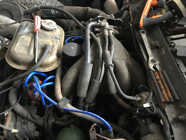
The Accelerated Idle Device is well and truly buried on an EFI car and like the CRC gets very little air time when discussing the BVH setup. It's sole purpose is to lower the idle speed when you put your foot on the brake. On a carby car it forms part of the carburetor itself but on an EFI its a separate unit bolted to the side of the engine roughly where the pressure regulator would normally be. You can just see it under all the hoses to the left of the aux air valve

48413369866_82c1d4511c_z.jpg


With the AAV out of the way our treasure is revealed

48413312871_2638f73fd5_c.jpg


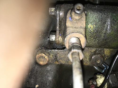
It's held onto the block by two m7 bolts that are impossible to see from the top and a hydraulic line that comes from the passenger side brake caliper.

33750151168_8c29816e0e.jpg


Whoever thought that it was a good idea to locate the bleed screw for the front left caliper here clearly was having an off day. With all the air hoses, coolant hoses and hydraulic lines in place there is no room at all to get a spanner onto it.

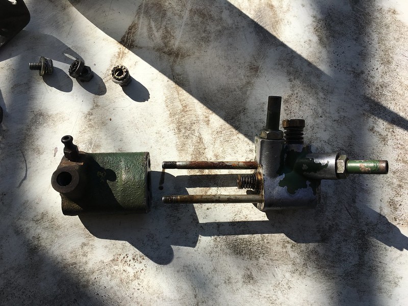
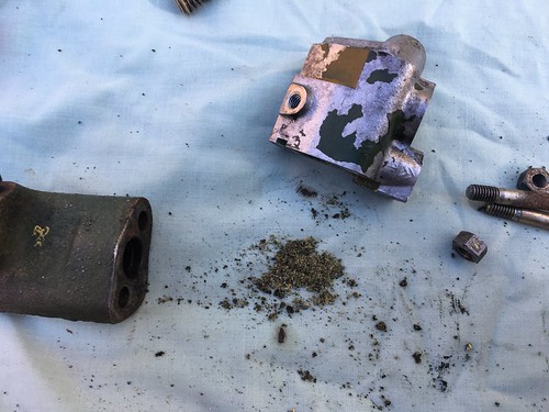
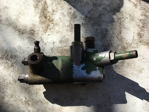
The unit itself is pretty straight forward with the two halves being held together by the two studs you can see on the left side of the unit and a single bolt on the back.

With those undone the unit simply slides apart. Keep an eye on the spring loaded piston so it doesn't launch itself.

47627442891_28af441f23_c.jpg


Internally it's pretty simple. High pressures arrives from the brakes on the left and acts on a piston to close the spring loaded air valve on the right. With everything set up properly the engine speed should now drop by approx 250rpm causing the clutch to disengage. Taking your foot off the brakes removed the pressure and the spring now forces the air valve back open increasing engine speed to the point where the car will creep forward in gear. The big brass screw on the right is for adjusting the secondary idle.

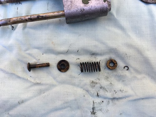
The air valve is made up of a few parts all held in place by a tiny circlip
40661064933_99fb8c0193.jpg


Looking into the air side of the unit revealed it to be completely blocked by debris. I've no idea what it was but it was packed in pretty hard. I counted the number of turns needed to remove the idle screw thinking this should make it easier to set up the BVH again later on. It's no wonder there were always problems getting the car to behave properly.

33750154668_758c9d394f.jpg


All clean and back together, with a bit of luck it will now work! Interestingly there is no oring on the hydraulic side of the unit. Any leaks past the piston will drain out a slot machined into the mating faces and drip down the side of the engine. A new pipe seal and its ready to go back on. Refitting is straightforward if a bit fiddly

47627435831_5e046b03ee.jpg


As a side note, is anyone interested in a step by step trouble shooting for for Djetronic specific to the DS?
 
Does this car have a Smiths Valve as well like the SM has? It would be good to understand how the Smiths Valve, the AAV and the brake valve all work together to manage the idle control system. I have fitted a BX idle control valve instead of the AAV which is mounted on one of the heads of my SM because It is jammed in a partial open position as well as being pretty inaccessible.

Cheers, Ken
 
Nice post. Did you also find the slide valve inside the hydraulic half of the accelerated idling device? It looks like this:

Orientation of slide valve in body copy.jpg
 
I've not heard of a smiths valve but I'm going to say the DS doesn't have one. The AAV and accelerated idle device are part of two different systems and work independently of each other. Think of the AAV as performing the same function as a choke. The BHV system relies on having two idle speeds to function properly and this is where the accelerated idle device comes in.

Dismantling the AAV will be covered soon as replacements are ruinously expensive and despite what most say they're very easy to dismantle. Essentially it's a temperature controlled air valve that lifts the cold idle to 1000rpm by allowing extra air to enter the inlet manifold. When the coolant temp hits 70deg or thereabout it should be fully closed and stay that way otherwise the engine speed will start to see-saw as the rev limiter cuts in.

I did find the slide valve in the hydraulic half but forgot to take a picture of it. There was nothing wrong with it so I just washed out the bore and piston in petrol, coated in LHM and reassembled.
 
I did find the slide valve in the hydraulic half but forgot to take a picture of it. There was nothing wrong with it so I just washed out the bore and piston in petrol, coated in LHM and reassembled.

Well done. Thought it might have been gummed up and stuck in the bore.......
 
Thanks Paul, I'm glad someone is finding this interesting. I've been reading through your blog a fair bit to rebuild the hydraulic components and cylinder head.


Hi Faulksy,

You can be sure that many of us find these posts extremely interesting and the photos even more so. The various restoration threads and similar threads elsewhere on AF are such a great resource when we get down and dirty on our own cars.

Keep up the great work and I think you definitely deserve an OAM - Order of Aussiefrogs Medal for sheer persistence, plus I can't believe how much you get done in a very short time. I must be the slowest self-directed mechanic in Australia, it seems to take forever to get stuff done here.

regards leconte
 
Thanks Leconte. Some weeks it feels like nothing has happened and then suddenly a whole bunch of work happens.

As promised, here is a guide for taking apart the much maligned auxiliary air valve. For such a simple unit, it cops a lot of stick from most people who own an injected DS and rightly so. It is prone to jamming fully open, fully closed and anywhere in between. In addition it can leak coolant into the inlet airways and down the side of the engine.

Its mode of failure is pretty easy to determine based on what problem the car is having. Jammed open will allow to much air into the engine once it has warmed up causing the engine to rev up to 1800ish RPM, hit the idle rev limiter and drop back to 900ish rpm endlessly. Jammed closed will make the car hard to start on cold mornings without giving the accelerator a boot full once the engine catches. Leaking coolant into the engine is pretty rare but could happen with the associated consequences. It lives on the side of the engine roughly where the pressure regulator would be and is pretty much impossible to see through the tangle of EFI wiring, fuel hoses and air hoses. With everything in place this is what you get

46251511624_2e78cd8750_z.jpg


It's roughly in the space between the no. 2 & 3 inlet runners. Digging a bit deeper reveals the unit.

48413369866_82c1d4511c.jpg


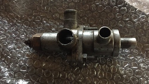
It's fixed into a bracket on the side of the block and is held in place one nut on top and bottom. I've found deep drive sockets to be the best option as the studs are rather long. Without all the hoses the unit looks like this

46062216295_57d51ee7a8.jpg


On the left is usually where the sender for the temperature warning light is fitted. The two left ports connect to coolant lines and the two right ports connect to air lines. The two halves are bolted together with a gasket to ensure a watertight seal. The right side housing the air slide valve is that part the causes the problems. The hole unit is pressed together and gives no clues about how to dismantle. As you'll see in a bit, the port on the end is part of a much larger machined sleeve. I'm borrowing this image from another thread here to show how the two halves come apart. Even separated the right side is a sealed unit.

48622013073_5e0606a508.jpg


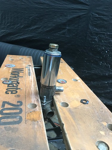
There are various suggestions on other forums on how to get it apart ranging from smashing the brass bulb with a hammer to force the end out to using complicated and very expensive pullers. I decided on a slightly different approach. Set 1 is to run an 11mm tap down the hose barb on the far right end. Make sure that you tap the full length of the hose barb other wise it will snap off in the next step. There is plenty of room inside to run the tap into past the hose barb.

For the next part you'll need a 25mm deep socket. The deep part is important as you'll see in a minute. Grap an M11 bolt and a couple of nuts, make sure the bolt is long enough to screw all the way down past the bottom of the hose barb. The aim is for the large flat section at the bottom of the barb to take most of the force not the barb which will snap off.

33100371748_7ac7bedc45.jpg


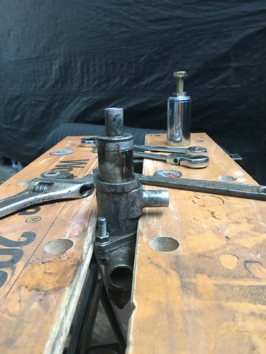
Using the old two spanner trick wind the bottom nut against the socket to pull the sleeve out of the housing. .

40011280663_149b7d9406.jpg


The top 5mm are ever so slightly wider then the rest of the part which is what holds the whole thing together. With the sleeve and piston out of the way you can put a socket into the bore and tap out the boss holding the thermo element. There's not much inside. They work much like a thermostat. Wax in the brass bulb expands and pushes the piston against the spring closing the stepped opening in the side of the sleeve eventually cutting off air flow.

32034825687_c9fb37ba4c.jpg
.

I found the inside of the sleeve was very rough. The edge of the piston isn't chamfered so the sharp edge digs into the sleeve and the whole thing jams. The problem is worsened by any dirt that gets pulled into the unit. A quick and very light sanding with some 1200 grit paper sorted the sleeve and a bit of light filing took the edge off the piston. The thermo elements can die and putting it into some boiling water will soon show if it needs replacing. It only moves about 10mm and is pressed into the boss at the bottom of the unit.

To reassemble use a vice or similar to press the thermo element back in. Then insert the piston and spring and then the sleeve. Press the whole unit together until the sleeve hits the bottom of the bore. Place the thermo element into nearly boiling water to confirm the unit works. It should be fully closed at about 75deg.
 
Episode 16: Sorting the BVH system part 1

Because of where the fire started and burned hottest all of the components of the BHV system bore the full brunt of the blaze. Given the system was still holding pressure a couple of days after the fire I rather hoped the components had escaped relatively unscathed as I didn't fancy trying to find replacements. If you dig into the parts catalogues, IE cars have different parts fitted to the standard production cars. There are very few IE BVH cars in Australia as fuel injection was first offered in late 1969 and the BVH was banned under the ADRs in 1971 giving a very small window to import one. Add to this the cost of the fuel injection and it's not surprising there aren't many here.

First up was the Clutch Re-engagement Control. A fun little device that modulates the clutch engagement speed based on throttle position. It also has two secondary functions. With the selector in neutral, it limits how far the throttle can be opened making it impossible to rev the car higher than about 1200 rpm. Its final job is to close the throttle during gear changes allowing the driver to keep their foot planted on the accelerator and maintain relatively smooth shirting. On an IE car it lives on the inlet manifold over the exhaust. There is usually a drip tray and heat shield under it to give a bit of protection or in my case, start a fire.

48524081806_73da2f45d2.jpg


The one that I took off the car was blackened to a crisp and the shaft was seized suggesting it had gotten very hot. Dismantling is very similar to taking apart the pressure regulator and was pretty painless until I had to get the slide valve out. After trying all manner of options I had to resort to a drift and sledge hammer........clearly this unit was finished. There was no corrosion on the piston or bore so something has warped internally.


I had to visit Denton Christie in Penrith about some other parts and he gave me free reign on the parts cars. One of which happened to be a DS21 IE still possessing most of the parts.

48524083496_9a51bb233a_z.jpg


Take 2, following in the footsteps of Paul Restoration of a 1968 Citroen DS21bvh Pallas: CRC Unit (Clutch Re-engagement Control) - Strip Down and Overhaul the unit was quickly stripped down ready for cleaning

48524075351_142499bc60_c.jpg


There are a couple of differences to the standard unit. The mounts and pipework, there is no flow restricting ball bearing and spring and the springs inside are supposedly different. The new seals were easy to install with the biggest challenge being getting the adjuster to grab the key and start winding it in. Of interest was that on this unit the adjuster was wound in 18 turns whereas on the original on it was wound in 13 turns. I reset it to 18 as the car it cam off apparently drove just fine so we shall see.
 
Last edited:
Well done! The trickiest part I found was the smaller two-part slide valve with the spring in between. very difficult to align before the sealing cap goes back on..... 'Locking' the rotating shaft against it's spring action isn't tricky, but it's possible to lock it in the wrong position (i.e. pin not in the locking hole but just against the cam).

Regards
Paul
 
That slide valve was somewhat fiddly to reassemble, trial and error finally got there though. I had considered replacing both the springs but decided removing the shaft and cam to be one step to far in an effort to minimise interference with the factory settings.The hope is that it will all go back together and just work. I was slightly surprised at the state of the o-rings in the seal plate, they were completely deformed and blocked. It's a wonder the thing worked at all.
 
Episode 15: Progress Report

To many things have happened in the last 2 weeks to sensibly split them out so here goes.

The new EFI loom went in and each component was checked against the manual to make sure it was all working. During the tests I found that I had incorrectly wired the impulse relay but that was soon fixed. Safe in the knowlege that all the components tested ok I felt safe to connect the ECU and begin testing. After being burned and flooded there was no guarrantee the ECU would even power up let alone work particularly as I had to desolder the resistor bank at the top of the photo to get all the water out. The scary thing is, there is no way for the average Joe to test an ECU beyond putting power to it and seeing if the pump runs.

48413269106_c05cf134a1_c.jpg

Low and behold plugging it in and turning the key caused the pump to run and opening the throttle produces the requisite 20 clicks from the injectors, both good signs. I also had to install a NOS manifold vacuum sensor which cropped up on ebay for just over $100 AUD as the original on was full of water and cactus. Not bad going given they usually start at 500 EUR for untested ones from a field. Given it was dead I decided to open it, not something that should normally be done.


48413552886_5a92c70e37.jpg

The rust is from the iron core of the transformer and armature. I might reinstall it later and see what happens.

I ended up chasing my tail around the engine for 2 weeks trying to figure out why it wouldn't start. Checking all the usual things like points and such turned up no answers and the starter motor had to be sent off for rebuilding. It came back looking brand new and turns over about 5 times faster than it used to. Still no life from the engine. I did get it running on 2 cylinders briefly one afternoon but sadly that trick was not to be repeated. I concluded that the ECU must be damaged and tracked down a mob in Melbourne who can test and repair them. It passed every test with flying colours somewhat annoyingly as it meant the problem was elsewhere. A chance discovery revealed that the points were sticking and not following the cam properly. A new set was installed and it fired into life!
 
Episode 16: Sorting The BVH system part 2

With the engine running it's time to sort the rest of the hydraulics. Seeing as I still had many pipe connections undone I left the regulator bleed screw undone to limit the amount of fluid that could flow further back into the system.

Next on the hit list is the centrifugal regulator. Once more Citroen throws a spanner in the works by specifying a different part for EFI cars. I believe the difference is the springs on the governor but details are thin on the ground. Interestingly, how many would have guessed that fuel injected DS21s got the same sodium filled valves as the SM? The centrifugal regulator is what gives a BVH car the ability to creep like an automatic. As engine revs rise from the slow idle to the fast idle the governor acts on a slide valve letting progressively more fluid return from the clutch slave to the tank and brings the clutch up to the biting point. With everything set up properly the car will now creep forward or backward depending on gear. It should also stop the car rolling back on hill starts.

48669371661_2f07969134.jpg


It comes apart into three assemblies, the centrifugal governor, clutch slide valve and anti stall device. For a change there are very few parts inside. The two nuts on the right are in fact two studs that hold the two castings together. Undoing them reveals a spring and piston.

48669026188_62c1b11499_z.jpg


There are 3 bolts that hold the front casing on which need to be undone to get at the slide valve the governor bears on.


48669025743_2d01e0f446.jpg


The front bearing seemed fine so I left the governor well alone. There are only 2 seals to be replaced in the unit, one where the front casing joins the centre section and one for the main piston. The anti stall piston at the rear relies on a paper gasket to seal the backplate. They're all very easy to get at and replace.

48669368966_24225f7a19.jpg


Cleaned and reassembled. You can see the slide valve on the cloth at the top. The new silent blocs were a proper pain the install. The tolerance is very small and they require a huge amount of force to press in. With that done, the governor can go back on and the unit is ready to be reinstalled on the engine.
 
Nice one. Accepting that there is a ring seal inside the bore, des the (anti-stall) piston at the back end of yours move freely? I have two regulators (one of which is rebuilt for my car) and on both the pistons are extremely tight in the bore. It would take a fair amount of pressure to move the piston against it's spring. I suspect the pistons may be too tight.....

I'm not sure whether they are meant to slide gradually and smoothly/ easily under low/building pressure - for example when you gradually slow down - or whether they are meant to generally offer resistance but then move fast and suddenly to prevent a stall - like when you do an emergency stop. Any idea?
 
It was a couple of weeks ago I was doing this but from memory the piston was stiff but moved freely. I think the anti stall piston is only meant to operate in an emergency stop. If you jam your foot onto the brakes the spool valves will fully open and have the potential to put the full system pressure of 150bar (2500 PSI give or take) into the front brake circuit. Rear brake pressure never gets that high as the suspension circuits feeding them run at a lower pressure.

I think under normal circumstances, it is the drop in engine RPM that will cause declutching via the governor.

Thanks for your thoughts faulksy. I guess the principle is that, in an emergency stop, that back piston compresses against its spring (or does it move the other way?) . In doing so, it creates more room (less room?) in the body of the regulator and the slide valve that controls the feed to the clutch moves (one way or the other!) and disengages the clutch independently of the governor? Something like that.....

So presumably the piston should not be so stiff that the big spring cannot 'reset' it after an emergency stop?
 
Top