Particularly in a FWD application where there is drive shafts and suspension in the road. He. Road.
Just trying to understand the load these humble triangles end up with.
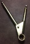
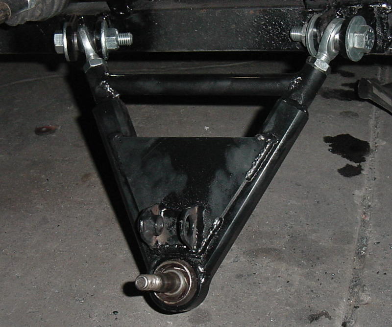
Apart from locking the wheel in location, and with the aid of a ball joint allowing it (the wheel) to rotate left and right, whilst the inside edge of the control arm mounted to the chassis, provides for rotation up and down, I quickly see the lower control arm is really a clever little sod that does a great deal.
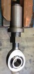
Under acceleration, would it be fair to say weight is transferred to the front chassis locating point of the control arm as the drive shaft tries to twist everything forwards, and under deceleration the rear as the twisting force is stopped? I confess I'm struggling to see how the lower ball joint could transfer much weight either direction but images of really beeffy box section style lower control arms, would seem to indicate to me there is significant load bearing these parts are required to handle?
Just trying to understand the load these humble triangles end up with.
Apart from locking the wheel in location, and with the aid of a ball joint allowing it (the wheel) to rotate left and right, whilst the inside edge of the control arm mounted to the chassis, provides for rotation up and down, I quickly see the lower control arm is really a clever little sod that does a great deal.
Under acceleration, would it be fair to say weight is transferred to the front chassis locating point of the control arm as the drive shaft tries to twist everything forwards, and under deceleration the rear as the twisting force is stopped? I confess I'm struggling to see how the lower ball joint could transfer much weight either direction but images of really beeffy box section style lower control arms, would seem to indicate to me there is significant load bearing these parts are required to handle?
")