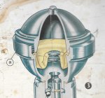
D-Special Sphere rebuild

OK, here's a revision of my first concept.

The only addition I may consider is to make the end pieces of the cradle able to clamp the sphere in position, say by the larger one having the full 360 deg hole and the smaller one with a clamping bar.

The cradle itself can be clamped or bolted to the bed of the press, or such large object as is needed.

Otherwise I've taken into account the comments so far.

Let me know what we all reckon please.

Cheers, Pottsy

Maybe, use a material thicker than 4mm to give you more surface area to grip with. If you are going to turn the inside, you might as well make it wider and cut a step. That will also help position the clamps more positively.

Are you going to add a gusset to the cradle uprights to stop them bending?

If you are using a press to move it, do you plan to move it a few degrees, unclamp one clamp, move it around to position for the next press stroke and reclamp before pressing a few more degrees? Or am I misunderstanding the proposal?

Another way might be a ring gear and pinion if you want mechanical advantage without using a length of water pipe. If the ring gear is wider than the pinion, you can clamp it together once and accommodate the unscrewing of the two halves. You could possibly do the same with a worm drive, but to keep it in mesh it would probably need to act on the 'driven' clamp via some pegs.
 
Last edited:
I think the tool is way too thin as proposed. A thicker "edge" for clamping, in addition to the use of coarse valve grinding paste for more grip, will get you started on the unscrewing. Have seen well stuck spheres even test a tool made from half inch plate.
 
OK, here's a revision of my first concept.

The only addition I may consider is to make the end pieces of the cradle able to clamp the sphere in position, say by the larger one having the full 360 deg hole and the smaller one with a clamping bar.

The cradle itself can be clamped or bolted to the bed of the press, or such large object as is needed.

Otherwise I've taken into account the comments so far.

Let me know what we all reckon please.

Cheers, Pottsy

Looking at your drawing, you will be putting a lot of force onto the filler neck when the press comes into play. . .

I would be working with two square plates with the appropriate circumference certres removed. Grub screws at close intervals on the centre flats. The lower square held in a 6" vice, the upper with a four welded verticals that can be used to set a lever to unscrew the top section, initial crack with a suitable mallet on the verticals.

Cheers
Chris
 
A good lesson from Chimbu's burst accumulator thread.

Darrin's comparison is for the suspension spheres, while the 2-piece accumulator is about 2/3rds that size. Is there a quoted volume?

Did pas become a standard fitting after 1972? It would always have had the 7 piston pump. Is that a better test for 62 vs 40 Bar than the absence/presence of the brake accumulator?

Haven't found a volume for the accumulator but this shows the difference side by side with a suspension sphere

61780d1413172184-sphere-removal-tips-accululator-rear-sphere.jpg


Just looking at an old ad of Richo's, he described his accumulator sphere as being gassed at 65 bar suitable for all LHM cars 66 - 75 with power steering DS and ID.

Cheers
Chris
 
Thanks guys. Taking the concerns expressed in turn.

The actual flat areas on the two halves of the sphere are the determining factor of the amount of grip, and therefore the thickness of the clamps, in my opinion.

Anything thicker will indeed need to be stepped as suggested, and that's an excellent thought, but the contact area perpendicular to the clamping force is still only going to be about 5mm max. Look at Chris's pictures and you'll see that the clamping area on the male half (the top bit with the filler) is only narrow.

Thinking about it, I guess I could grip the lower part by the centre band, which would allow a wider clamp, but the flat bit on the part that has to unscrew is still thin. For some reason my head was focussed on clamping the thin flat band on the female half, but the wide band makes much more sense.

You never stop learning! :)

As far as the force on the filling screw is concerned, the part it screws into is a tapered bit and I was planning on countersinking the part that holds that so the shear force would be on the sphere half rather than the bolt.

And yes, using the press was how I envisaged making the first unscrewing movement over a couple of mm, then relocating the clamp.

Thanks for the feedback chaps. This could be the first special tool ever designed by a Committee! (Scary thought)

Keep the discussion going, it's very entertaining.

Cheers, Pottsy
 
Gripping it only by the wide area is possibly an error because the tighter you clamp it, the more you compress the threaded area and make it that little bit more difficult to undo. The areas you have chosen to grip would be the logical ones to use if you can grip then effectively.

I think you will be moving the clamp quite a few times as it's not likely to suddenly let go so you can unscrew the rest by hand. If you just want the press to 'crack' the thread, maybe it will work, but it's likely to be quite tight for a few turns. You might want to provide some pegs in the driven clamp ring so be able to turn it with a bar/rod.

What is said bout committees, horses and camels?
 
Pottsy,

I don't quite understand what you mean regarding the support for the filler port. You are going to need quite a bit of downward force to unscrew the two halves, I would think you would need to support that half of the sphere, which to me would mean some sort of bearing to allow the turning movement. Also some protection of the thread on the other half :confused:

If you look at the pic of the two spheres above, note evidence of grub screws on the suspension sphere, I know you would like to leave no evidence but you may need to get a stronger grip than you will achieve by simply clamping.

I fully understand how Bob has achieved a successful oucome, but feel you may have slippage for little result - you may get lucky on some spheres. . .

Thought bubbles :wink2:

Cheers
Chris
 
The plug isn't very large or deep, they typically have a wedge cut out of them and may have been chewed with pliers, so your cradle will need to be very stiff to avoid it spreading and the sphere moving down, maybe suddenly. The threads are all the same, so you might do better to screw the sphere into a main support and then support it only in the middle with a cradle???
 
The plug isn't very large or deep, they typically have a wedge cut out of them and may have been chewed with pliers, so your cradle will need to be very stiff to avoid it spreading and the sphere moving down, maybe suddenly. The threads are all the same, so you might do better to screw the sphere into a main support and then support it only in the middle with a cradle???

Food for thought. I can see version 5 forming in the cerebrum.

Thanks chaps. More anon.

Pottsy
 
I think you are still very much underestimating the forces needed on some spheres, and overestimating the strength/rigidity of fabricated steel.

Why have you offset the clamping bolts away from each other?
With the clamp bolts directly in the line of the clamp disc, there is no tendency to warp the clamp.
Also I think its a big advantage to get the fixed support boss as close to the line of pressing as possible. If anything I would offset the bolts towards each other, not away.

In my experience, the split ring clamp does "shrink" the sphere female thread enough to make it seem tight to undo.
I find that it needs to be tight to get enough grip to start the undo, then I loosen the clamp a fair bit, for the rest of the unscrewing, usually just by hand on the flogging boss.

OTOH the grub screw gripping one I use on the acc spheres does not "shrink" the female as much, getting grip from the hollow cones of the grub screw points. You need to use good quality grub screws with a sharp hollow conical point, and accurate Allen sockets.

It might be worth considering grub screw grip for both clamps.

I still reckon a removable long handle, with a face to assist with a hammer is the go.
If you have bench space I'd consider mounting one clamp on the bench with the sphere axis vertical, the other clamp with the handle, swinging horizontally around the room.

For reassembly, I find that clean and lubricated threads will easily screw together with gentle finger grip, only requiring "power" to tighten the last 1/4 turn. You can feel when it closes up metal to metal inside, if you use a method of applying torque with feel, like a long handle.

Using a powered press you could exert way too much closing torque...... could this be a cause of cracks leading to failure?
 
Pottsy,

While the pdf is a great exercise in using a drawing program - the tools will not work. Will make this simple

1) The collar or 'clamp' for the upper (male) portion of the sphere, to work correctly, needs a set of four hardened pointed set screws that are sequentially tightened against the narrow ridge of metal just above the threaded area. Lacking those set screws the holding collar will just slip.

2) Almost impossible to grip, with a collar, the lower half (female) sphere body as the gripping area you are referring to in your drawings is not flat - but quite concaved in shape. Possible if one has the right machinery to mill a mating surface to fit. But why bother.

I posted some time ago the tools I use, based on a lot of experimentation years ago, and proven in use for some 13 years now of how it is done. And the same basic design that Bill used when he got into sphere rebuilding. FWIW the filling head Bill used was one I made for him.

Once the upper half of the sphere is secured and the holder placed in a well bolted bench vise, the units are quite easily opened up with the use of large chain wrench (plumber type). The major 'force', if you will, that tends to hold those things together is the formation of a bit to a lot of rust in the upper threaded areas. A good number of spheres will come apart with hardly any pressure applied via that chain wrench. If not, then one needs to 'shock' the threads with 3 or 4 well placed blows from a hammer on the outer ring of the lower sphere half, followed up with the addition of a good penetrating oil that is allowed to seep in over a few hours time.

One needs to be aware that the threads used on those spheres are:

1) Just shy of what is known as an 'interference' fit. IOW any major compression of the that outer ring will cause them to bind up.

2) They are not 'square' cut threads - they are cut at a 45 degree angle to maximize their holding strength when the sphere is pressurized and in service.

When re-assembling the two halves with the new diaphragm in place you hand tighten the upper half until it just contacts the diaphragm's upper sealing lip. Then you only give the upper half between 1/8 to 1/4 (at most) turn to affect a good seal - no more.

Once re-charged you place the unit in water to inspect for any gas leakage. If done correctly you will not have any :). OTOH gas leakage from the threaded area can be caused by both insufficient as well as to much pressure on the diaphragms sealing lip in addition to just plain problems with the sealing lan faces on either the upper/lower or both sphere halves. The other problem with over tightening is reduced service life of the diaphragm itself. To actually affect the threading one would have to tighten the two halves to the point that the diaphragm's elastomer was basically destroyed.

Steve
 
Last edited:
I have managed to open five spheres and fitted new bladders.
With great difficulty for some.
As noted above, the threads are cut like a saw blade, not symmetric.
I bent a heavy duty crowbar and completely failed to undo two of them.
In hindsight, I think the problem is not with tight or rusty threads, but with the pressure due to the growth over time in the density of the bladder material, especially with the LHS bladders. Natural rubber can grow up to around ten per cent of original size over time.
The threads do not tighten down metal to metal, only on to the O ring part of the bladder.
Inspection of the threads when removed reveal that apart from the outer turn of thread, they are quite clean and not binding, therefore the problem seems to be from excessive pressure on the threads from growth of the O rings.


I would not , from experience, use a tool that grips unevenly, like stillsons, nor a rig that uses grub screws.


It may be worth trying to make a rig that actually squeezes the two halves together, lightening the binding load on the lands of the threads, before unscrewing.


Rex

Rex - the factory got away from 'natural' rubber eons ago :). From about 63 on the LHS bladders were constructed of EPDM rubber. Will not swell, at all, in the presents of a glycol based fluid (LHS). And the problem of hard to open spheres (if they have not been damaged by a previous attempt to open) has always in my experience (based on doing a couple of hundred of these suckers over the years) been a slight bit of rust/corrosion of those threads. As I said in the post above, you need to grip the upper half of the sphere with a collar equipped with 4 hardened steel set screws that have a pointed end. The unit is then unscrewed with a large self gripping chain wrench - minimizes any compression to the female threads of the lower half of the sphere.

The factory did some unfortunate rubber formulation experimentation with LHM bladders in the 70's. In most locals they worked just fine - retained N2 pressure better than the previous generation. OTOH in really hot climates they would turn to a googy, soggy mess. Can post some pics if anyone is interested.

Now I have had more than just some old LHS units (and rear LHM) that required some 'shock' treatment and the addition of penetrating oil along with heat before they would open. The cause in all cases was visible rust on the threads after the spheres were apart. And it can just take the form of just noticeable discoloration of the metal. Does not have to be a deep red color to cause problems. If the oxidation has reach the point - opening can be a real struggle.

Steve
 
I can just make out that camel masquerading as the committee's horse coming into view ...

The thread takes the form of a buttress thread, but probably has a more precise designation:
https://en.wikipedia.org/wiki/Buttress_thread

Rex's LHS spheres from a derelict ID might be more difficult to open than those from Pottsy's LHM Special.

There are obviously a number of ways to address this. Here's another. This YouTube video shows a mount with three grub screws on a bench leg to hold an accumulator sphere, then opened using a chain wrench (and a length of water pipe):
https://www.youtube.com/watch?v=AEUTyzbC1Wo
I guess opinions will vary about whether this setup can be improved on and whether it's possible to do this job without any bruising of the metal.
 
I can just make out that camel masquerading as the committee's horse coming into view ...

There are obviously a number of ways to address this. Here's another. This YouTube video shows a mount with three grub screws on a bench leg to hold an accumulator sphere, then opened using a chain wrench (and a length of water pipe):
https://www.youtube.com/watch?v=AEUTyzbC1Wo
I guess opinions will vary about whether this setup can be improved on and whether it's possible to do this job without any bruising of the metal.

Brilliant thanks David, the jig is a little like I had envisioned but held in a vice, the chain wrench is the go, on the flat of the sphere :headbang:

Cheers
Chris
 
Remember too. The metal used in spheres is very, very soft. It will be readily damaged by un-even forces. Hardeneded tools readily damage the steel. I've used chisels on the throw away spheres many times. The metal is so soft you can take big chunks out of the spheres even using cheap (ie:soft) screwdrivers as the chisel.

seeya,
Shane L
 
I can just make out that camel masquerading as the committee's horse coming into view ...

The thread takes the form of a buttress thread, but probably has a more precise designation:
https://en.wikipedia.org/wiki/Buttress_thread

Rex's LHS spheres from a derelict ID might be more difficult to open than those from Pottsy's LHM Special.

There are obviously a number of ways to address this. Here's another. This YouTube video shows a mount with three grub screws on a bench leg to hold an accumulator sphere, then opened using a chain wrench (and a length of water pipe):
https://www.youtube.com/watch?v=AEUTyzbC1Wo
I guess opinions will vary about whether this setup can be improved on and whether it's possible to do this job without any bruising of the metal.

Dave,

Brake accumulator spheres are dead easy to open as they, typically are completely protected from the environment. The 'mistake' in that video is the use of that bloody clamping style chain wrench. And for exactly the reasons above. If one uses a self locking chain wrench (no clamping) those brake accumulators typically just spin off - even LHS ones unless the fluid in the car as been allowed to get really water contaminated. I first tried just a locking collar on the upper sphere half many, many moons ago. And it would work on units that were reasonably easy to disassemble. OTOH given a sphere where just the least bit of corrosion had occurred with in the threads and it would not hold. Just physically insufficient surface area to work with.

And if one is that worried about the little indentations that are going to be left by the set screws, a bit of body filler and a quick wipe with sand paper and they are gone.

On my bench, as I write, are 5 brake accumulators (3 D and two Maserati Bora Units) as well as two really rusted (exterior) old LHS spheres from a USA 66 car. The 5 brake units were apart in about a total of 10 minutes. The LHS front suspension units took about 4 hours as I had to shock the threads with a 1 KG hammer/apply penetrating oil and let them sit for 4 hours. Once done they came apart with out much trouble. If not pre-treated they might still have been separable - but why fight it :)

Steve
 
Pottsy,

................... The other problem with over tightening is reduced service life of the diaphragm itself. To actually affect the threading one would have to tighten the two halves to the point that the diaphragm's elastomer was basically destroyed.

Steve

The sphere closure does make metal to metal contact.

Sphere 2.jpg

It is carefully designed to give correct compression of the elastomer (normally 10% for O-Rings)
It should be tightened until you "feel" the metal to metal contact.
If you pre-assemble a sphere without the diaphragm, you will easily feel the point where the metal seat faces contact, Then mark this with 2 small centre punch dots, on the rims.
This way, when you do the final assembly you can easily check that you have tightened it correctly.

The damage caused by overtightening is not to the elastomer, it is to the stress point at the base of the female thread....... which as we know, can lead to cracking.

Edit. PS: You really must lubricate the diaphragm rim liberally with the appropriate fluid, so during the final tightening, the male part slides smoothly over the "O-Ring", without trying to tear it.
 
Last edited:
............
The threads do not tighten down metal to metal, only on to the O ring part of the bladder.
Inspection of the threads when removed reveal that apart from the outer turn of thread, they are quite clean and not binding, therefore the problem seems to be from excessive pressure on the threads from growth of the O rings.

I would not , from experience, use a tool that grips unevenly, like stillsons, nor a rig that uses grub screws..........

Rex

See my previous post about closure......

The grub screw tools work very well, and the more grub screws the better. I have used 6 in my acc tool, but could even suggest more, maybe 8 in a suspension sphere tool. By using many, and gently tightening them in several stages, prevents significant distortion of the sphere circular shape. and minimises "compressive shrink", and greatly improves grip.


I shudder when I come across a sphere that has been butchered with Stilsons or cold chisel..... UGGGGGHHHHH!
 
The sphere closure does make metal to metal contact.

View attachment 80693

It is carefully designed to give correct compression of the elastomer (normally 10% for O-Rings)
It should be tightened until you "feel" the metal to metal contact.
If you pre-assemble a sphere without the diaphragm, you will easily feel the point where the metal seat faces contact, Then mark this with 2 small centre punch dots, on the rims.
This way, when you do the final assembly you can easily check that you have tightened it correctly.

The damage caused by overtightening is not to the elastomer, it is to the stress point at the base of the female thread....... which as we know, can lead to cracking.

Edit. PS: You really must lubricate the diaphragm rim liberally with the appropriate fluid, so during the final tightening, the male part slides smoothly over the "O-Ring", without trying to tear it.

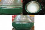
Bob - If you are getting metal to metal contact then there is something very wrong with the construction of the diaphragms you are using. See the composite I just made. I grabbed a couple of sphere pieces out of my collection and put your theory to the test. The photo in the upper left shows the two halves hand tight with no diaphragm. I put a punch mark on the upper half and a scratch mark of the face of the lower half to denote position. Look at the number of threads showing - just one thread. The upper right photo shows a standard Desmopan diaphragm. Now look carefully at the bottom middle photo. Again the upper and lower halves have been hand tightened.Note that the punch mark on the upper half is about 1/16th turn beyond its position the no diaphragm position. However there are now TWO threads showing. From that point one would tighten the upper half another 1/3rd turn to effect a good seal. And we are still going to be just about 3/4 of a turn from metal to metal contact.

But thank you for mentioning lubrication :) - quite necessary to prevent damage to diaphragm as the upper half is tightened down. For LHM systems one could use LHM or a high quality wheel bearing grease. For LHS you need Castor Oil. The later has become quite cheap as it has now become all the rage with people as a hand lotion and health nuts (at least in the US).

Steve

Composite.jpg
 
Last edited:
Top