
You are using an out of date browser. It may not display this or other websites correctly.
You should upgrade or use an alternative browser.
You should upgrade or use an alternative browser.
807 11 ~ Electric coolant pump?
- Thread starter RINGER
- Start date
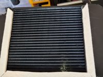
Well the radiator turned up overnight from Melbourne!
Quite small & though described as 4 row is 2 row but looks like double width of a normal row?
This is going to be experimental as it has no where near damaged radiator capacity.
Alternator & cam pulley set up ratio about 4:1 so should be fine.
Pick up elec coolant pump tomorrow then away till Friday then pick up water jetted coolant block to replace original coolant pump.
Hopefully this weekend will put everything to bed - radiator is the only question mark @ this time. JG.
Coolant block sounds interesting, would like a couple of pics if possible
Will do. Thanks for your input. JG.Coolant block sounds interesting, would like a couple of pics if possible
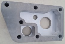
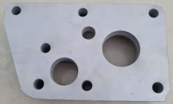
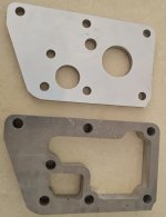
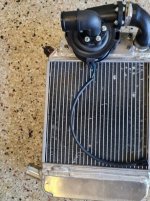
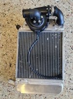
Just a tickler ~ here are some photos of the water jetted coolant plenum box to replace the original water pump ~ 25mm & 32mm 90º angle coolant pipe will be welded to the cover plate, that is cut from 10mm aluminium plate, @ suitable angles to meet the Davies Craig 80l/min variable coolant pump & return from the head to radiator. Smaller centre hole is to be tapped 1/4NSP for the electric pump temperature sensor/controller.
The other water jetted piece to the cylinder head is 20mm aluminium plate. All up water jet cost $80.
The other water jetted piece to the cylinder head is 20mm aluminium plate. All up water jet cost $80.
Attachments
Last edited:
Nice work!
Funny thing is the Mini Cooper radiator for a 1275 GT has a coolant capacity just under the radiator taken out [think it was Austin 1800].
I'm going to cut & enlarge both headers by about 50mm & fit 32mm in & out so this volume increase will have absolutely plenty of coolant. Probably around 2l more than the 1800 had, so I'll keep my fingers crossed there is enough finned surface area to dissipate the heat quickly enough.
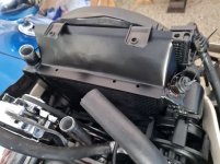
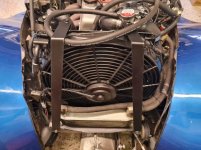
Will be fabricating a tight fitting shroud to ensure that huge fan up front gets all the CFM through the right area.
I'm going to cut & enlarge both headers by about 50mm & fit 32mm in & out so this volume increase will have absolutely plenty of coolant. Probably around 2l more than the 1800 had, so I'll keep my fingers crossed there is enough finned surface area to dissipate the heat quickly enough.
Will be fabricating a tight fitting shroud to ensure that huge fan up front gets all the CFM through the right area.


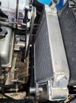
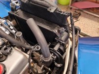
Here is the radiator I'm modifying new tanks & end pieces cut, shaped ready for welding next week.
All will then be ready for a restart with the newly fitted electric coolant pump. JG.
It will be interesting to see the difference when its all together. The later technology with the alloy rad should dissipate heat more efficiently than the old 1800 unit.
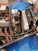
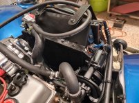
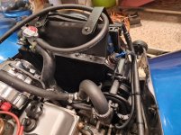
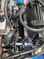
Got a lot done today all in & fitted ~ when all finished I'll assemble method in better order.
To do is complete mounting top & bottom & fabricate shroud. Forgot the coolant heat under carb & that is a pain, now all the aluminium welding is done!
To do is complete mounting top & bottom & fabricate shroud. Forgot the coolant heat under carb & that is a pain, now all the aluminium welding is done!
Attachments
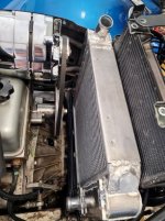
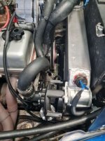
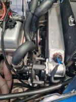
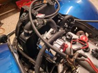
Here are the welded manifold, before I cleaned up & the extended coolant tanks giving over double coolant capacity, nearly 3 litres.


Lots done today just about there ~ stopped taking coolant @ about 4+ a little litres so has an air lock somewhere. Mad a shrouds & sealed with felt so that fan should be working better than ever before & cooling was never an issue.
Attachments
-
 20211006_122710.jpg61.1 KB · Views: 116
 -
 20211006_152938.jpg48 KB · Views: 117
 -
 20211006_160826.jpg64 KB · Views: 115
 -
 20211007_172041.jpg61.2 KB · Views: 121
 -
 20211007_172112.jpg60.2 KB · Views: 118
 -
 20211007_172142.jpg62.6 KB · Views: 116
 -
 20211007_172148.jpg70.6 KB · Views: 121
 -
 20211007_172059.jpg60.5 KB · Views: 115
Fabulous. Really pleased.
Ran over an hour today.
Warmed up very quickly & topped off coolant as air removed from the cooling system.
Pump cycled on & off maintaining precisely 88*C.
Turn off & pump kept working until 80*C
Then shut down.
Will adjust temp to run on about 95*C - system pressure is 1.1bar, 110 kpa or 16 psi.
Any ideas?
looks like a success to me! That shut down feature is very kind to our old engines.
Is the 95C for the pump and fan ? I set my pump at 80 and fan slightly less, they run off different thermostats and sensors, only because I already had the fan before the EWP setup.
I get a bit more power with a lower temp in the coolant out of the head. I believe a higher temp gives better fuel economy.
3 sensors - Fan turns on & off through head temp & radiator top tank also A/C switched.
EWP sensor is also on return from head to top tank.
EWP sensor is also on return from head to top tank.
I also would also prefer to see it run 80-85 degrees, and if at 88 now I would leave it alone or look to reduce slightly. Newer cars do run at higher temps, I expect for emission and economy. Given the gains are minimal at the higher temps, I would still want to run your engine in the 80s.3 sensors - Fan turns on & off through head temp & radiator top tank also A/C switched.
EWP sensor is also on return from head to top tank.
I have one of the Davies Craig aluminium EWPs on my old BMW race car. The amount of coolant it moves is incredible. It is claimed to be 115L per min, and looks it when watching the coolant flow across the top of the radiator with the cap off.
What is the oil pressure sender unit thread into the engine block of an 807 - 11 engine, please?
Don't have much room between engine & Light 15's frame rail so may have to get a good 90* male female fitting.
Sender unit suggested to KUS digital gauge is:
KUS ~ P/N SAW-40025 Measuring Range 0-10bar Alarm 0.8±0.2bar Thread 1/8" NPT Volts 6V/24V Output Signal 10-184 Ohm
I'm pretty sure the current sender is not properly matched to the new KUS digital gauge.
Pressures seem to be reading far too low on a relatively newly rebuilt engine [before I bought & really, really clean inside top & bottom]
EG. especially @ warm idle, like 0.8 bar & about 2.5 - 3bar @ RPM warm.
About 5bar on cold start up.
What should one expect?
Not having a master gauge I will get a matching sender & keep fingers crossed for now. JG.
The oil pressure sender thread size is M14 x 1.5What is the oil pressure sender unit thread into the engine block of an 807 - 11 engine, please?
Don't have much room between engine & Light 15's frame rail so may have to get a good 90* male female fitting.
Sender unit suggested to KUS digital gauge is:
KUS ~ P/N SAW-40025 Measuring Range 0-10bar Alarm 0.8±0.2bar Thread 1/8" NPT Volts 6V/24V Output Signal 10-184 Ohm
I'm pretty sure the current sender is not properly matched to the new KUS digital gauge.
Pressures seem to be reading far too low on a relatively newly rebuilt engine [before I bought & really, really clean inside top & bottom]
EG. especially @ warm idle, like 0.8 bar & about 2.5 - 3bar @ RPM warm.
About 5bar on cold start up.
What should one expect?
Not having a master gauge I will get a matching sender & keep fingers crossed for now. JG.
The Coriolis effect?The entry point of the swirl tank is in the centre of the container so how does the coolant swirl, thinking about the oil tanks on open wheeler cars.