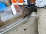
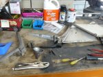
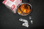
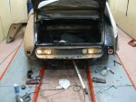
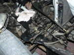
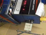
Ah~......... Untracked air outlet and speed meter surrounding plastic! Nice!
Nice!
Nice! Nice!
Nice!") ... I guess fitting new captive nuts and burying it all in grease would stop it rusting again. ... As for the car looking great ............. It's good the photos hide so much :roflmao: ). I'll see how much those reproduction brackets GB has listed above are though. I've found these always get destroyed once you remove them from cars too.... No matter how well you try to store them
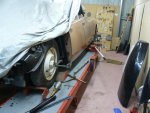
... I guess fitting new captive nuts and burying it all in grease would stop it rusting again. ... As for the car looking great ............. It's good the photos hide so much :roflmao: ). I'll see how much those reproduction brackets GB has listed above are though. I've found these always get destroyed once you remove them from cars too.... No matter how well you try to store them One day, in the not too distant future, you're going to finish this car...a potentially traumatic experience???
Bruce.
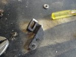
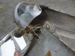
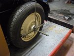
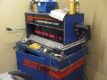
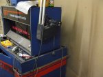
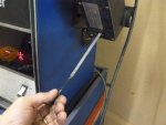
). I couldnt' understand how they worked. one "wheel prop" on each is how they were setup. I can assume they were using the aligner by just pulling the lines back to the rear wheels like this.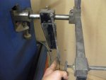
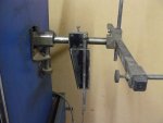
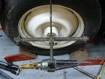
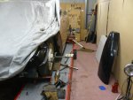
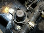
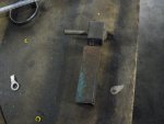 The lower track rod looks like it doesn't unbolt They must have been different on the other ID19 .... or maybe I'll pulled the whole trackrod through the relay... hmmmm..... Oh well it's all fun right
 Pull the relays apart and do the job properly.
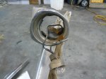
All early Dees has the lower arm attached to the relay arm. The upper and lower relay arms on power steering cars were a different length from those on manual steering cars. Try to find some power steering ones. It is not easy.
Roger
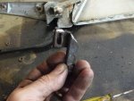
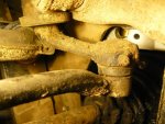
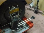
I can't remember. I want to keep these ones on the car, the relays and track rods appear to have no wear at all.... so I'd like to keep the mechanical bits from this car in place (I dont' think this car has done many miles from new given the lack of wear on everything !).