External Regulator

Big Frog

Active member
Fellow Frogger
Joined
Sep 4, 2012
Messages
439
Location
Somewhere near Mudgee, NSW
Hi All
My external Regulator on the 69 - 70? D has spat it.
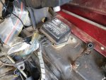
I have another external regulator that I could try to use , it is new.
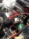
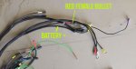
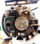
Attached is a photo of the back of the Alt.
Terminals are :
+ this goes to the Battery directly
EXC this has the yellow spade connector to it (i'm guessing this is for the exciter circuit)
- is for the earth connection
IND is for ? maybe for the dash lamp? This is not currently connected & my dash lamp does not function correctly, always on.

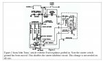
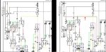
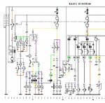
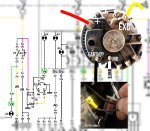
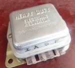
The external reg has four terminals ( and is similar to those used on old falcons)
Terminals are:
F
S
A
I

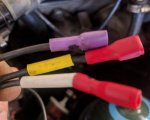
The wires I have to the old reg are red and Mauve.

Any tips would be grand.

Steve
 

Attachments

  • DUC REG.jpg
    DUC REG.jpg
    238.5 KB · Views: 346
Oh and I have this diagram, so I guess I'm trying to reconcile this with the reg and Alt I have
 

Attachments

  • wiring diagram croped.jpg
    wiring diagram croped.jpg
    455.8 KB · Views: 402
The reason your charge lamp won't go out is the white wire is missing on the regulator. It's possible that the screw worked loose and fell out.

Ind may be the rotor winding, does it have voltage whenever the ignition is on or just when the alternator is spinning?
 
Hi Steve, The Ind terminal on the Alt. goes to the centre tap of the 3 phase winding (inside the alt. ) and will have an output of 7V when charging, it is used to operate a normally closed relay to turn off the charging light. The wire from your dash lamp must be earthed in order for it to stay on!
 
Hi Faulksy,
Ok I found a white (marked wire with connector) that would go onto the terminal marked IND on the Alternator.
In as much as the fitting on the Alt matches the wire fitting type, the Alt is original to the model, and the harness is a new replacement for the model.
So it would seem i have the ALT connections matched as per the diagram.
The Battery wire, yellow spade and white lug wires all come from the harness together.
The White marked wire has continuity to the white wire at the Reg
The Yellow marked wire has continuity to the Yellow marked wire at the Reg.

So at the reg I have the three wires shown in photo.
And these make sense in terms of the diagram.

I can't see the Red marked wire from the diagram that would go to the dash lamp?
And next I have to figure out which wires go where on the new regulator - pictured.?

The regulator is a type that is used in old Ford Mustangs etc.
But trying to find info online is difficult
Steve
 

Attachments

  • wiring-alt connections.jpg
    wiring-alt connections.jpg
    269.1 KB · Views: 1,256
  • 3 wires at reg.jpg
    3 wires at reg.jpg
    50.5 KB · Views: 263
  • reg.jpg
    reg.jpg
    103.3 KB · Views: 271
Hi Brian,
I understand what you are saying here, and that may in fact work, but the wiring diagram shows the dash lamp wire going to the REG not the ALT?
This is part of my confusion.
Steve


Hi Steve, The Ind terminal on the Alt. goes to the centre tap of the 3 phase winding (inside the alt. ) and will have an output of 7V when charging, it is used to operate a normally closed relay to turn off the charging light. The wire from your dash lamp must be earthed in order for it to stay on!
 
Seems like all the wires are there but perhaps in the wrong places.

Mauve is key switched +12V and connects to the voltage reg BOB terminal
Yellow connects the EXC terminal of the voltage reg to the EXC terminal of the alternator
Red connects the dashboard lamp to the voltage regulator L terminal. If you ground this wire with the key on, the lamp should come on.
White connects the R terminal of the voltage reg to the Ind (I think) terminal of the alternator

As far as swapping in the ford voltage reg goes I think this is what needs to happen
EXC to F (yellow)
IND to S (white)
A to BOB (mauve)
I to L (red)

Be careful playing with the wiring around the alternator and voltage regulator as only the mauve and red wires are fused.
 
Hi
You are on the right track! Based on my 68, here are the connections between a Ducellier alternator and original voltage regulator. Principles are the same for later cars.

'Exc' on the alternator connects to 'exc' on the regulator
'Ind' on the alternator connects to 'R' (the middle terminal) on the regulator
'+' on the alternator connects to the positive terminal of the battery
'-' on the alternator doesn't get used. i'm told it could be use for a rev counter or suppressor if wanted.

"L" on the voltage regulator goes to the charge warning light of the dashboard
"Bob" on the voltage regulator goes to the ignition switch

I also found this image. Hope this helps with aligning things to your replacement regulator. 'I' would seem to be the old 'Bob', but all three other connections seem to want to go to the alternator? I'm sure the people who have fitted modern alternators with internal regulators to their Ds have solved this puzzle.

VR.jpeg
 
Okay. My theory (from the diagram above) about 'I' on your new VR being 'Bob' is at odds with what Faulksy says in an earlier post :)
On my hard drive i found a short note and photo - probably lifted from a note on a forum somewhere. The note says "Fit a Ford external regulator (e.g. 1982 Ford Mustang) "I,A,S,F" terminals of Ford Regulator go to wires "L, Bat, R and EXC" from Citroen Voltage Regulator. It is also possible to fit an aftermarket miniature Ford voltage regulator inside the OEM regulator can." That SEEMS to be saying that I equals L, A equals 'bat', S equals R and F equals 'exc'........
 
Seems like all the wires are there but perhaps in the wrong places.

Mauve is key switched +12V and connects to the voltage reg BOB terminal
Yellow connects the EXC terminal of the voltage reg to the EXC terminal of the alternator
Red connects the dashboard lamp to the voltage regulator L terminal. If you ground this wire with the key on, the lamp should come on.
White connects the R terminal of the voltage reg to the Ind (I think) terminal of the alternator

As far as swapping in the ford voltage reg goes I think this is what needs to happen
EXC to F (yellow)
IND to S (white)
A to BOB (mauve)
I to L (red)

Be careful playing with the wiring around the alternator and voltage regulator as only the mauve and red wires are fused.


Attached is diagram from an article on putting one of these Ford Regs in an original style Regulator case.. > http://citroen.cappyfabrics.com/Regulator.pdf

It agrees with your view, its odd however the IND marking on the alternator never appears in the diagrams?
Somehow French for Stator must be IND something?
 

Attachments

  • enclose.JPG
    enclose.JPG
    98.8 KB · Views: 315
I'd imagine the electrical section of 814 would be a lot thicker if they listed out every combination of parts fitted accross the different export markets. Have a look at the windscreen wiper wiring on the diagram and compare it to your car sometime..........

"R" on Paris Rhone alternators stands for "rotor". It appears the Americans refer to it as the stator, Bosch use a different name as well. Same thing just different names. Seeing as there wasn't really a standard for automotive electrics the various companies made it up as they went, Citroen for instance use black as the color code for +12V where every other field of electronics uses black for ground.
 
You're correct, I recall fitting my new wiring harness and the wiper connections were unlike the diagrams etc...
Now my only problem is locating the Red wire that is supposed to run back to the dash lamp!
 
It should come out of the loom along with the rest of the voltage regulator wires. Originally would have been a ring terminal but who knows with a new wiring loom.

Out of curiosity, what happened to the original regulator?
 
The original original one - dunno, there was something else on it when I got the car, that failed and a Bosch RE55 replaced it.
The RE55 is a 2 terminal sold state thing. I don't possess a version of the original mechanical type.
 
Hi again Steve, As I said earlier the wire from the Ind terminal operates a normally closed relay, in the original this was inside the metal Reg box. The wire from the ind light goes to the relay and is connected to earth until the relay is activated by the alternator. Any small 12 v change over relay will do.
Woody
 
Make sure you don't have a BVH car. The Ford (IASF) regulator is not compatible with the wiring for a BVH car unless you ground the wand switch independently behind the dash. Otherwise it should be a simple swap.


Citroen Terminal​
Ford Terminal​
L​
I​
BOB​
A​
R​
S​
EXC​
F​


Find the Citroen “L” wire, which goes to the warning lamp on the dashboard (If you don’t know which wire, have an assistant look at the instrument panel with the key on as you test the regulator wires by grounding briefly). Attach this wire to the “I” terminal of the Ford regulator.

Next, find the EXC terminal on the alternator. On the DS it is a blade terminal at the top of the case. On the SM it is a blade terminal near the positive post. Wire this terminal to the “F” terminal of the Ford regulator.

Next, find the half-rectified terminal on the alternator. On the SM it is the only small post sticking through the plastic grill. On the DS it is the larger of the two small posts sticking out of the back of the alternator, the other post is a ground, so if you have any doubt, check with a multimeter. The ground post will have continuity to ground, the half-rectified post will not. Attach a wire from this post to the “S” terminal of the Ford regulator.

Finally, connect 12V power to the “A” terminal of the Ford regulator. This can be switched or un-switched, but should be fused if you use un-switched power. The BOB wire is switched power from the ignition switch.
 
If you want to make it look "original" you can get a cheap Transpo F7078 miniature Ford regulator and mount it inside the case (after you gut it and clip the wire wound resistors underneath. )

Transpo_F7078.jpg
 
Thanks for the info John on the Ford Reg hookup. Thanks also Brian.

So I have figured out or rather recalled an issue from the original harness install, it was a new harness 2 years ago, and it was fitted just before a bush trip and time was short.
The harness supplied is for my year model which should have had the Start solenoid on the battery terminal, my car has a newer replacement starter with the solenoid at the starter. And possibly it was a harness for a BVH car, which is not what I ordered, but by the time that was discovered it was well and truly in the car.

The reason that I can't find the Red wire back to the dash lamp is that it was pressed into service as the wire to the Starter solenoid, as there was not one in that harness.
So I need to run a wire for the lamp separately and proceed.
At the time I posted re this with the attached difference in the wiring diagrams, attached
cheers
Steve
 

Attachments

  • Start-compare.jpg
    Start-compare.jpg
    199.3 KB · Views: 204
I’m assuming your car is a manual gear change. If that is the case, it would never have been fitted with a solenoid at the battery terminal. Instead there would have been a flying lead going straight from the ignition switch White wire to the starter motor. I think it would haven been on the drivers side of the engine bay. There is no interaction between the charge lamp and


As you discovered in the other thread, a BVH car needs the solenoid at the battery terminal to reverse the polarity of the starter switch. The wire that connects onto the battery mounted solenoid is a 2mm red sleeved female bullet. It goes into the main loom with the oil pressure switch wire, through the starter switch on the gear shift and reappears at a red sleeved ring connector to connect to the voltage reg. This is the brown wire you pointed out on the right hand wiring diagram. The dashboard light is spliced into this wire somewhere in the main loom behind the dashboard.

The charge lamp gets +12v from the instrument cluster which is why it only has one wire in the loom. connecting the charge lamp wire to the starter will cause it crank endlessly as long as the battery is connected and the ignition is on. Did you have to alter the new loom at all to get the starter to work with the key?
 
Hi Faulksy,
Yes the car is manual, when I got the car it had the battery terminal solenoid, see photo from pre-purchase.
In any case that harness is long gone, and by the looks of the rest of it, it had been chopped and changed - A LOT.

BTW, you asked about the original regulator, attached is a pic of the REG installed when I got the car, interestingly it is the type with terminals the same as the replacement I now have. So the old loom had a battery mounted solenoid and had been made to work with the Ford type external regulator, so someone had modified it.

So I got supplied with a wiring harness for a BVH car in error, back when I did the new harness.
The new harness has not been cut or modified in any way, just plugged into things a bit differently.
I found a photo of the brand new harness, part of which is shown attached.
The red bullet connector is beside the Battery wire, the one you mention.

So the red wire that would have attached to a regulator, is connected in the engine bay to the starter solenoid wire.
The other end of that wire is connected to the starter switch, but to the lug for the starter. ( not sure)
The Red Bullet Female connector wire is attached to the battery and from memory the other end is also to the ignition switch.

I haven't looked into the ignition switch to check how it was plugged in, however this what i came up with at the time to get it working without hacking the loom. I understand what you are saying about the power from the lamp activating the starter, but that doesn't happen so I will have to see exactly how I did it.
Steve
 

Attachments

  • batt.JPG
    batt.JPG
    229.9 KB · Views: 232
  • org-reg-sml.jpg
    org-reg-sml.jpg
    79.3 KB · Views: 229
  • wtf-note.jpg
    wtf-note.jpg
    219 KB · Views: 296
Top