Citroen Light 15 Rear Axle

RINGER

Well-known member
VIP Paid Subscriber
Fellow Frogger
Joined
Mar 25, 2018
Messages
1,740
Location
Robina, QLD.
In the next weeks I will be fabricating a new rear axle for my 1949 Light 15 to incorporate the existing torsion bar system plus disc caliper mounting brackets.
If anyone is interested I can picture & document what I'm doing & give dimensions?
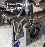
The reason I'm doing this is that the current axle has been modified by others over eons & after spending about $300 on wheel alignments, the last being FOC @ a truck shop that bends axles only to be told they couldn't do it ~ there is 5.1° total toe on the rear with the drivers side 4.6° ~ I decided it would be cheaper to setup & build a new axle from scratch.
Bought complete axle, hubs & bearings from Swiftco ~ 45mm solid beam for $223 & will water-jet the 2 axle to torsion arm brackets & the 2 caliper brackets. All up I reckon it will be about $500.
Please advise. John.
 
Hi John :)
Interesting idea. I assume you are aware that the axle is specifically built as flexible torsionally but stiff in bending in two directions. Your new axle should probably be the same for the rear suspension to work as it was designed. A 45mm square beam seems to be unlikely to act so and would act as an infinite stiff roll bar at the rear.o_O
There is a person on the central coast who had his axle bent by a tow truck when the car was pulled out by a rope on the beam. I believe he straightened it OK himself. I could give you his contact details if you want, PM me.
Jaahn
 
My car was 'very agriculturally' modified & somehow engineered by a really well respected company in mid western NSW.
This is a picture of the original mod, plus the new one to fit rear disc brakes.
I need the precise PCD of the 8 bolts inside the arrow ~ it is 88-90mm but really hard to measure in situ ~
Anyone have something on the floor or bench, may help?
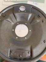
Brake backing plate with 6 drillings may have the same PCD ~ don't know but can y'all help.

Citroen Rear Axle (1).JPG
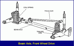
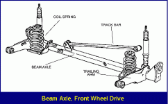
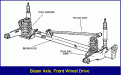
This is similar to what is planned, but with original torsion rather than coil springs.

rear-suspensions3.gif
 
Last edited:
Please does anyone have access to an axle removed from a vehicle & could please give me an accurate measurement for the PCD of the 8 holes that the torsion bar trailing arm attaches to ~ 88-90mm.
I did a shadow drawing by removing all the bolts but need something more accurate.
The holes in the plates I'm having water jetted need to be tapped & must align perfectly with those in the torsion bar trailing arm.
 
----------

View attachment 128347
This is similar to what is planned, but with original torsion rather than coil springs.

View attachment 128349
Hi :)
Just some comments on this proposed 'new' conversion of the 'old' conversion. I have been 'Conversing' directly with Ringer so this is directed at other people to comment on.
The Traction rear axle in its final form was designed as torsionally flexible and stiff in bending. There are warnings in the manual about lifting with a jack and only using a cradle to avoid damage. In my opinion the design of the suspension relies on the ability of the beam to twist so the wheels can move individually up and down and allow the arms to move in opposite angles as the beam twists. This also happens as the car rolls when cornering. Without this flexibility the suspension would be compromised to some degree.IMHO.
So a tube type beam with high torsional stiffness would be undesirable for several reasons. Would anyone like to comment on this aspect of the proposal to use a tube beam.
Jaahn
 
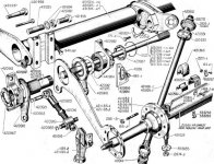
The twisting action is achieved in the flatness of the trailing arms. They are only around 6mm thick. The beam axle itself is quite rigid due to its cruciform shape but as you said can twist slightly longitudinally. These lessons were learned by the failures experienced in the very early designs of the Stage 1 variant of rear suspension. This variety has a rigid tubular axle beam and very light forged trailing arms. they used to wear their pivot bearings quickly. The second stage is the one that most of us are familiar with, utilizing silentblocs and only one Panhard rod. It solved the wear problems and also reduced the unsprung weight.
 
The twisting action is achieved in the flatness of the trailing arms. They are only around 6mm thick. The beam axle itself is quite rigid due to its cruciform shape but as you said can twist slightly longitudinally. These lessons were learned by the failures experienced in the very early designs of the Stage 1 variant of rear suspension. This variety has a rigid tubular axle beam and very light forged trailing arms. they used to wear their pivot bearings quickly. The second stage is the one that most of us are familiar with, utilizing silentblocs and only one Panhard rod. It solved the wear problems and also reduced the unsprung weight.
Stage 2 is what my vehicle has & I agree with Gerry regarding the trailing arms twisting & not the tube per se.
There may be slight axle twist but the torsion arms don't allow this axle rotation. Why there are 8 bolts?
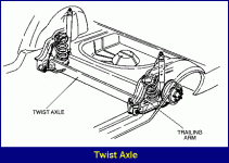
This system is totally unlike modern arrangements that do use various shapes connecting the trailing arms & are specifically designed to twist & called twist axles.

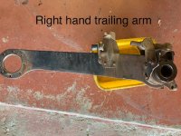
Just got off the phone with a friend with 2 light 15's. Both have only 6 holes in the backing plate on 100mm PCD plus his torsion bar arms have 8 holes but like me he can't get an accurate enough [88-90mm] measurement.

IMG_2777.jpgIMG_3182.jpg


rear-suspensions3.gifrear-suspensions4.gif

Just like ours solid beam & panhard ~~~~~ Modern twist axle
 
If your friend has that trailing arm an accurate measurement is easy enough with a vernier caliper. Measure the diameter of the set screw hole, and then measure across the diameter of the circle of holes from the insides of the opposite set screw holes. Then add one measurement of the set screw hole to that diameter and halve the result. This will be the radius of the pitch circle. All you need!
BTW that back plate is for the front swivels.
 
We're aware of how to measure the PCD but the arm is not off the car just a stored picture of when it was.
If anyone else has either side arm off they can help & how Gerry describes measuring is great.
So front & rear backing plates are different? That is good to know & I can see one is more deeply dished, whilst the other is not,
Thanks JG.
 
Last edited:
The twisting action is achieved in the flatness of the trailing arms. They are only around 6mm thick. The beam axle itself is quite rigid due to its cruciform shape but as you said can twist slightly longitudinally. These lessons were learned by the failures experienced in the very early designs of the Stage 1 variant of rear suspension. This variety has a rigid tubular axle beam and very light forged trailing arms. they used to wear their pivot bearings quickly. The second stage is the one that most of us are familiar with, utilizing silentblocs and only one Panhard rod. It solved the wear problems and also reduced the unsprung weight.
Hi Gerry and Ringer :)
I will not labor this point again but just state it once more for those who wish to learn !

The trailing arms are flat so they can twist and the axle beam is made of the thin flat bars made into a cruciform X shape to have little twisting resistance but strong in bending both ways.

If you imagine one rear wheel fully up to the bump and the other side fully down to the limit, then the up trailing arm is angled up so the arm is twisted as is the axle. But on the opposite down side the arm is twisted the opposite way and the axle is twisted that end opposite also. Check that if you want to.

It make no difference to me if you choose to make the axle as per your plan. Your choice really. But I just put the salient facts before you to help you avoid a problem. Like Citroen had in the original designs of their axle. You are welcome to learn the hard way also !

In the original VW beetles that had a similar design of torsion bar spring and flat thin trailing arm, the twisting of the stiff axle tube was accommodated by the use of a spherical 'bell' joint onto the side of the diff housing. If you jack up a Beetle you can clearly see the twisting of the axle tube on the diff housing and that is only looking at one side suspension moving.
Jaahn
You will get no argument from me on that score. This is entirely correct. It is the big lesson learned from the initial version of rear suspension fitted to the 1934 cars. The tubular axle was much more resistant to the necessary twist that occurs when one wheel is up and the other wheel is down.
 
Feedback from Brooks Chapin:
"the horizontally aligned holes on the backing plate from my '53 Normale measure 96.1 mm across the outside of the holes and 79.5 across the inside, so a difference of 16.6 mm divided by 2 = 8.3 either added to 79.5 or subtracted from 96.1 = 87.8.
the more vertically aligned holes are slightly larger (.2-.3mm) probably elongated on the vertical axis from bouncing."

Any other suggestions or feedback appreciated. JG.
At Last! Well Done and congratulations on your persistence and patience!
 
Here is an update & more info ~ should be started Monday & completed ready to install early next week :~
Any addition input appreciated.

This is what I'm making.
All the brackets for the trailing arms & disc brake caliper mounting parts were water jetted & ready for welding.
I'll take pics as I go & post later.

Any additional thoughts?
The guy [professional shop] assembling & welding all the parts I bought & supplied didn't want to split the tube as he says it may deform.

The quote below stresses & reason for the split in the axle tube, that I have highlighted.
Then he said he might weld @ intervals along the split as he is making it.
Material is 40mm NB schedule 80 Seamless Stainless 304.

Found this on Science Direct:
Trailing arm and torsion bar spring with non-drive axle rear suspension (Figure 10.48) The coil springs normally intrude into the space which would be available for passengers or luggage, therefore torsion bar springs transversely installed in line with the pivots of the two trailing arms provide a much more compact form of suspension springing (Figure 10.48). During roll of the body, and also when the wheels on each side are deflected unequally, the axle beam is designed to be loaded torsionally, to increase the torsional flexibility and to reduce the stress in the material. The axle tube which forms the beam is split underneath along its full length. This acts as an anti-roll bar or stabilizer when the springs are unevenly deflected. The pivot for each trailing arm is a pair of rubber bushes pressed into each end of a transverse tube which forms a cross-member between the two longitudinal members of the floor structure of the body. The inner surface of the rubber bush is bonded to a hexagonal steel sleeve which is mounted on a boss welded to the outside of the trailing arm. In the centre of the trailing arm boss is a hexagonal hole which receives the similar shaped end of the torsion bar. To prevent relative movement between the male and female joint made between the boss and torsion bar, a bolt locked by a nut in a tapped radial hole in the boss presses against one of the flats on the torsion bar.

r45PEzh6mmBrzpSIcpr4YhVJVjI6cZJMpfvJeUt7EVNMy4bvJFjzJqVgoC_R8Hl6t2KKPHGS3XC1eoACtcsrUXlEx6uVb0-wQJDbrF5RVn0YSdRC5uwkWZuTkam6Q_5-pWX8iswV_N4E0yoflpzh=s0-d-e1-ft

Download full-size image
Fig. 10.48. Trailing arm and torsion bar spring with dead axle rear suspension
One torsion bar spring serves both suspension arms so that a hexagon is forged mid-way between the ends of the bar. It registers in a hexagonal hole formed in the steel collar inserted in and spot welded to the transverse tube that houses the torsion bar spring. Again the torsion bar and collar are secured by a radial bolt locked by a nut.
In the static laden position a typical total angular deflection of the spring would be 20° and at full bump about 35°. To give lateral support for the very flexible trailing arms a Panhard rod is diagonally positioned between the trailing arms so that it is anchored at one end to the axle beam and at the other end to the torsion bar tubular casing. All braking torque reaction is absorbed by both trailing arms.

21-9.jpgrear-suspensions3.gif
 

Attachments

  • 1134_001.pdf
    50.5 KB · Views: 255
Top