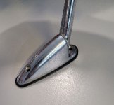
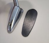
As you may know, I've been working with JohnW on a final run of mirror surrounds for R8/10. There are two types of mirrors and the surrounds fit the newer style perfectly, but are a little out if trying to use them on the older style of mirror. The workaround is to get a new piece of mirror glass cut, fit the surround, then glue the mirror to the existing one.
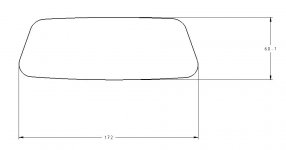
However, in order to get the glass cut to the correct size we would like to provide purchases the dimensions on a CAD file or possible a PDF output of same.
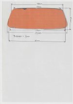
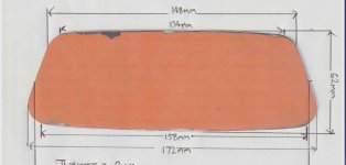
Here is a scan of the glass with some dimensions that we want, and I wonder if anyone could take this and turn it into a simple 2D CAD file and PDF output?
However, in order to get the glass cut to the correct size we would like to provide purchases the dimensions on a CAD file or possible a PDF output of same.
Here is a scan of the glass with some dimensions that we want, and I wonder if anyone could take this and turn it into a simple 2D CAD file and PDF output?