207 How do I remove the in cabin fuse box next to the glovebox

Krammig

Member
Tadpole
Joined
Jun 6, 2018
Messages
65
Location
Gold Coast
207 1.6L Petrol 2007 4 Door Hatch

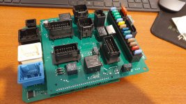
As I haven't been able to find a video or instructions I would appreciate if someone was able to point me to a video / tutorial on how to remove the in-cabin fuse box.

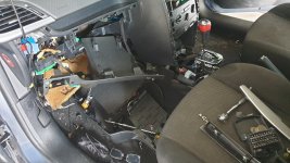
I have tried to fumble through but I just cannot work out how to get the whole thing out of that hole.

Thanks
 
Pull out from the bottom and slid down, some have 2 screws from the bottom.
Glove box needs to be removed.

This is the BSI or body computer you cannot swap with another why are you needing to remove?
 
I believe there are a few relays on the back side of this assembly and I am suspecting one of them might not be engaging correctly and causing the console cluster panel (speedo etc) to flicker and often just not work at all.
I've been trying to track down this problem on and off for months, just so frustrating because it is intermittent on my daughters car and concerned about her driving with no dials showing whenever it just decides to do that.
 
Try looking at the ignition switch 12v lead which powers console and lighting. Not much inside a BSI other than a couple of PCBs, you could check if any water damage from windscreen leaks etc
 
More likely to be the voltage regulator on the Instrument Cluster is suffering thermal overload shutdown, if cluster has already been changed then look for dodgy earth wire crimp.

For the BSI to be the culprit then AirCond ECU also would not work as it gets power from same fuse on the BSI.
You could try reseating or replacing Fuse 14 just to be sure.
BSI Fuse14 is responsible for
Instrument panel, seat belt warning lights bar, headlamp adjustment, air conditioning, hands-free kit, rear parking assistance control unit, air bags.
 
Thanks for the replies.

@AlexB I was planning on buying a second hand Instrument Cluster today and came back here just to check one more time, saw your reply so sorry for the late response.

You rightfully mentioned Fuse 14 as I tracked that down a while ago. What I noticed (my Daughters car) is that when the Instrument Cluster drops out, so does the Air Con. Makes sense as they both come from the same fuse.

What is confusing me is often the cluster will jitter and some lights may or may not flash, almost like a connection not quite making, other times it is totally off.
During the jittery time, the air con compressor will still not work. I assume not "constant" voltage.

As a gut feel do you think a problem on the main board of the Instrument Cluster could feed back and cause the Air Con issue as well, or would you say it is more likely something that is at the Input side to F 14 that would be the issue, and if so, any suggestions on where I could start looking ?

Thanks in advance.
 
If you swap the cluster the odometer reading may increase to whatever is stored in the cluster memory as the highest kms will always be displayed as method to reduce fake odometer readings.

Suspect a loose or damaged wiring if fuse connection is clean
 
@Krammig, the additional info of A/C also not functioning reduces probability of Instrument Cluster being at fault, and increases probability of a loose wire or crimp in the harness.
Both A/C and Cluster get 12v from BSI Fuse14 and wiring diagram shows both their ground wires eventually terminating at the same earth point, MC35, located near handbrake.
Find that earth, wiggle it and retighten has a high chance of fixing your symptoms.
If they persist then you'll have to pull the harness apart to find where the 12v and ground wires are joined and recrimp the joins.


207_MC35_earth.jpg
 
UPDATE

I have disassembled the inside of the car pretty much :)

Checked the Grounds (removed, cleaned with sandpaper), and checked as much cabling as I can.

My gut is telling me that it is the BSI, namely a relay on there. I'm about 87.3% confident of this.

Pulled the BSI, opened, and see that the top board is soldered to the bottom one unfortunately. In a video the chap had one that more or less clipped together, pins slotted in, rather then being soldered.
I was thinking of getting another BSI and just swapping across the top section containing the cable connector and relays etc but that would be an effort to un-solder those long side connectors.

My Questions ;

While I believe the ECU, BSI, Keys are all related and if replacing the ECU the BSI must accompany it ....

a)
As far as the BSI goes, can just I get another BSI with the same model number ( or doesn't the model number matter really ) and just put that is as a swap. ?

b)
Should I try un-soldering the top board ( pretty good at soldering ) and replacing the relays to give that a go.

I have seen what looks like a few dry joints and will be re-soldering those but not too hopeful that will make a difference.

Thanks for the feedback.

Cheers
 

Attachments

  • INT_H.jpg
    INT_H.jpg
    626 KB · Views: 89
  • BSI_H.jpg
    BSI_H.jpg
    552.2 KB · Views: 97
From experience of repairing these devils in a box. Some boards disconnect easily others are impossible.

You can't swap the BSI by itself as the car will never start again.

If you have PP2000 / Lexis and this model of BSI can be reset to factory and you have the key card you might have a fighting chance of doing it yourself.

The other option is to see if any local ECU repair place can clone the chip information from suspect BSI to replacement as that is the easiest option as no programming required.

And if you're thinking I'll just throw the BSI in your odometer will be changed to which ever unit has the highest kms so don't do it as you can't wind them back

PM me if you need other options
 
Thanks for that @dimistyle Yep suspected that was the case with a no-go on swapping the BSI, thanks for the confirmation.

I've just gone through and resoldered a few joints and sanded some pins that looked a bit off, but frankly they all look clean and the unit looks like new so I would be surprised if it was that sort of thing.

Appreciate the offer, I might well take you up on that. Cheers.
 
That is what is known as a CAN-CAN (or all CAN) BSI. The video was probably of an earlier CAN-VAN BSI. The upper and lower boards on the CAN-VAN BSIs were not soldered together.
The lower board contains the "brains" and the upper board contains the relays, connectors and fuses.
There are a number of ways to go. You can replace the faulty relay, replace the relay board, swap the EEPROM to a donor BSI or clone the EEPROM and reprogram the EEPROM on a donor board.
I would recommend obtaining another BSI and "fool around" with that before touching your original. If you bugger your original you are potentially up sh!t creek. Being a CAN-CAN BSI it is "easier" to reconstruct (if dead) than the older CAN-VAN units for reasons I wont go into. But you don't want to go down that path.
The processor on the BSI can "shift" the data around the EEPROM making cloning or moving the EEPROM impossible. I don't know if these do it or not. I don't think so.
As Dimi says, don't actually plug the donor BSI into your car!
I am only dabbling in this stuff at the moment and am not an expert.
There are plenty of "chip tuning" guys around but it's very difficult to find guys who can do this stuff.
It's a very long story but my son needed to reprogram the engine ECU in his Rodeo after an engine change. It look him over a month to find a guy and the guy was booked out for two weeks! You cant find these guys in the yellow pages!
 
Top