How to make a brand new plastic French steering wheel.

56 Fregate

Well-known member
VIP Paid Subscriber
Fellow Frogger
Joined
Oct 31, 2010
Messages
38,102
Location
Beautiful New England
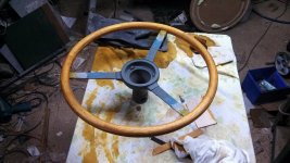
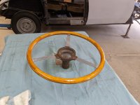
Some time ago I built a new steering wheel which was a direct copy of an original but alas, I don't like the feel of it. The diameter was too big and the rim of the wheel was too chunky and doesn't feel very good in the hands. I set-out to modify the timber pattern I'd made previously and have another lash. Over the next couple of weeks I will get it finished and show the steps along the way for those who might be interested.

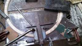
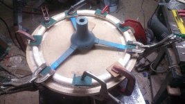
The timber (MDF) pattern was knocked up so a 2-part plaster mould can be made and a steel skeleton installed in the mould cavity. I'll need to wait for a week or so before I continue so the plaster can dry out, else it will react with the epoxy resin. In the mean time here are some images for your perusal..TBC

3.jpg
4.jpg
9.jpg
wire frame.jpg

IMG_6801.JPG
 
Graham what is the cost of doing this? I have an old fordson tractor that needs at least a new rim,I can buy a reproduction for about $80 and I've been wondering if it's worth having a crack at making one.
 
Just a recap. A couple of years ago I made this timber pattern and went through the steps to make it into a functional epoxy plastic steering wheel but I've since modified the pattern to a smaller diameter and here I go again. This is not my first rodeo..

8.jpg
10.jpg


I set it up in a round form made from timber and tin so I could make a two part plaster copy of the pattern which is quite a simple thing to do. After a few days drying the plaster was filled where necessary with wood filler to patch up any bubbles. Then the working surfaces were coated with epoxy resin to seal the plaster. I've found from experience that if the plaster is not sealed it will absorb the epoxy resin making extraction of the cast item from the plaster mould quite a job. I'm hoping this time the mould will release the completed steering wheel without too much of a fight. I fully expect that this mould will only ever yield one complete wheel. But that's alright because I only want one.

IMG_6845.JPG
IMG_6846.JPG
IMG_6847.JPG


A simple mild steel frame was welded up with a modified Renault Dauphine boss at the centre. I changed the taper and added a slot to suit a woodruff key. The rest was easy.

IMG_6829.JPG


Tomorrow I'll do a test close and test for clearances, then if all is good I will be ready pour in the epoxy resin.
 
Last edited:
Thanks for such a clear description of the process. Could you explain how to do a wood rim wheel? I've been thinking of getting one in a slightly smaller diameter for the fast Floride. ;)
 
Thanks for such a clear description of the process. Could you explain how to do a wood rim wheel? I've been thinking of getting one in a slightly smaller diameter for the fast Floride. ;)
You mean a smaller Moto-Lita style wheel? It would be quite simple to do if you can handle a router. If you are really keen I'll formulate a process for you.
 
Thanks for such a clear description of the process. Could you explain how to do a wood rim wheel? I've been thinking of getting one in a slightly smaller diameter for the fast Floride. ;)
I made a wood rim for our Riley RM as the plastic rim had cracked & looked bad. The wheel has a steel ring that is welded to the stainless steel spokes.
There are 2 ways of doing a wood rim. One is steam bending 2 pieces of timber into circles or making 2 circles out of many segments.
I did number 2 & this is how I did it.
First thing after the old plastic was removed from the wheel & the rim all cleaned up was to draw the segmented design in cad. This gave me the dimensions & angles of the required 64 pieces.
Some 65 x 20 Tassie Oak was ripped down into strips about 5mm thick. These went through the thicknesser so they all came out at an even 3mm. I made a jig to cut the strips on the table saw so they were all the same angle & shape.
Next was to glue up an octagonal shape with all the little bits. This had to be done 8 times as the wheel rim was being built up with 8 x 3mm thick segmented rings.
The thin segmented rings were cleaned of excess glue & sanded smooth. Next step was to glue 4 rings together to make something that resembled a plywood ring while ensuring that all the joins were staggered from the layer below (very important).
I used polyurethane glue & lots of baking paper for areas I didn't want the glue to stick to.
What you wind up with are 2 segmented rings about 12mm thick each. These are going to become either side of the wheel rim.

individual pieces sm.jpginitial layout sm.jpgglueing layer sm.jpg
 
Wood Rim next step.
I made up a circle cutting jig for the router and screwed a segmented ring down to the base. This way I could cut out the outside diameter & the inside diameter of the new rim. The little tabs were for the hold down screws & they were cut off by clamping the ring down onto the jig.
This gets done twice so you end up with 2 nice round plywood type rings albeit with sharp corners. Not really that good for a steering wheel yet.
While the rings were still in the jigs I used a bull nose bit to cut a semi circular groove into the rings right where the rim of the steering wheel was going to go. No picture of that though so you will just have to imagine it.

Next was to round over the rim. The router was turned unto a spindle moulder by mounting it upside down into convenient bench. Using a sharp router bit of the right radius, lots of little cuts, a great deal of care & much patience, the square edge rings turned into nice round rims.
You can see the result in the third picture with the 2 halves taped together. Inside the ring is the hidden circular groove that will take the steel ring of the wheel. If you look closely you can see where the cutout will be for the spokes to come through.

first routing sm.jpg2nd routing sm.jpgcurving rim sm.jpg
 
Next installment.
Next job was the fingergrips on the back.
I had drawn up the locations of the grooves in CAD & these were transferred to the new rim. Made up a jig that held a half round file & with the help of a few clamps & a bit of eyeballing I filed all the grooves in.
Now it was final assembly time. The front half of the wood rim sat on the original cutting board with the semi circular groove up. Lots of poly glue & the steering wheel metal rim was placed into the groove. More glue all over it & on the matching faces of the back half of the wood rim. All carefully aligned & clamped together. Glue came out everywhere but I expected that. Left it overnight for everything to cure.
Time to clean excess glue off, fine sand the rim & give it a stain as Tassie Oak is super light.
Last job was to paint the rim in 2 pack clear. It got about 6 coats with very fine sanding in between. The centre hub got its 2 pack brown & voila - a finished wood rim steering wheel.
My wife really wanted the wood rim look for the old girl & I wanted to give it a go.
It took a huge amount of work with an equally crazy amount of hours but I am really pleased with the end result.
 

Attachments

  • finger grips sm.jpg
    finger grips sm.jpg
    797.2 KB · Views: 120
  • gluing rim to wheel.jpg
    gluing rim to wheel.jpg
    684.4 KB · Views: 102
  • assembled & stained sm.jpg
    assembled & stained sm.jpg
    664.8 KB · Views: 113
  • steering wheel sm.jpg
    steering wheel sm.jpg
    388.7 KB · Views: 118
Bloody beautiful and well worth the hours invested. As we all know it isn't an option to consider paying someone else to do the job but if you have the skill and time, if you know what you want and are prepared to go for it, you can produce something spectacular. Well done ibartie..(y)
 
Next installment.
Next job was the fingergrips on the back.
I had drawn up the locations of the grooves in CAD & these were transferred to the new rim. Made up a jig that held a half round file & with the help of a few clamps & a bit of eyeballing I filed all the grooves in.
Now it was final assembly time. The front half of the wood rim sat on the original cutting board with the semi circular groove up. Lots of poly glue & the steering wheel metal rim was placed into the groove. More glue all over it & on the matching faces of the back half of the wood rim. All carefully aligned & clamped together. Glue came out everywhere but I expected that. Left it overnight for everything to cure.
Time to clean excess glue off, fine sand the rim & give it a stain as Tassie Oak is super light.
Last job was to paint the rim in 2 pack clear. It got about 6 coats with very fine sanding in between. The centre hub got its 2 pack brown & voila - a finished wood rim steering wheel.
My wife really wanted the wood rim look for the old girl & I wanted to give it a go.
It took a huge amount of work with an equally crazy amount of hours but I am really pleased with the end result.
Superb work. Congratulations.
 
Since my last installment I have set the steel frame into permanent position in the mould and conducted a test close of the mould to ensure nothing is touching. Prior to that I painted on two coats of release wax which I did in the hot sun to ensure the brush marks flatten out. The wax then sets hard as it cools. Attention was paid to the threaded centre bolt and associated hardware which I also coated with wax to aid in removal later on, fingers crossed. I then laid some skinny beads of acrylic gap filler as shown to reduce leakage from the mould, as it turned out I only had one fluid leak after pouring of the epoxy commenced, this will be a personal best for me. Plasticine was on hand to plug said leak. You will also notice the three small pins called chaplets installed in key locations, the sole purpose of which is to help the steel frame maintain proper clearance.

IMG_6862.JPG


IMG_6861.JPG


I poured the resin in while the whole shebang was in a vertical position, this aids the release of trapped air. The astute observer will of course have noticed the dandy little pouring funnel I carved in the plaster in readiness. A small quantity of resin is kept for topping up as the resin sinks in and most of the air bubbles find their way to the top. I fully expect to find small pockets of accumulated air or gas and other blemishes. In the next exciting episode I will explain how we deal with casting defects.

IMG_6865.JPG


IMG_6866.JPG
 
Last edited:
Since my last installment I have set the steel frame into permanent position in the mould and conducted a test close of the mould to ensure nothing is touching. Prior to that I painted on two coats of release wax which I did in the hot sun to ensure the brush marks flatten out. The wax then sets hard as it cools. Attention was paid to the threaded centre bolt and associated hardware which I also coated with wax to aid in removal later on, fingers crossed. I then laid some skinny beads of acrylic gap filler as shown to reduce leakage from the mould, as it turned out I only had one fluid leak after pouring of the epoxy commenced, this will be a personal best for me. Plasticine was on hand to plug said leak. You will also notice the three small pins called chaplets installed in key locations, the sole purpose of which is to help the steel frame maintain proper clearance.

View attachment 225307

View attachment 225306


I poured the resin in while the whole shebang was in a vertical position, this aids the release of trapped air. The astute observer will of course have noticed the dandy little pouring funnel I carved in the plaster in readiness. A small quantity of resin is kept for topping up as the resin sinks in and most of the air bubbles find their way to the top. I fully expect to find small pockets of accumulated air or gas and other blemishes. In the next exciting episode I will explain how we deal with casting defects.

View attachment 225309

View attachment 225308
Nice work as usual. We are agog waiting for the next episode.
 
Top