gererator to alternator conversion.......

56 Fregate

Well-known member
VIP Paid Subscriber
Fellow Frogger
Joined
Oct 31, 2010
Messages
38,102
Location
Beautiful New England
generator to alternator conversion.......

Can any of you sparkie froggers enlighten me as to weather I need to change the standard regulator when doing an alternator upgrade from a Renault fitted with an original generator? Any advice would be helpful.
 
Last edited:
You see that! ask the right questions and you get the right answers.

You will definitely be removing the existing dynamo regulator and doing some rewiring.

If you choose one of the earlier Renault Alternators as a replacement, i.e. off 12 or 16 you will need to use the existing external regulator.

If you go for a modern alternator the regulator will be inbuilt and you don't need an external regulator.

FWIW my choice of alternator would be a 80 amp Bosch unit off a VT Commodore. It has an Inbuilt regulator and minimal wiring changes are needed. You will need to change the VT pulley and fit a vee section pulley. You will need to work out the new mounting and tensioning arrangements.

I can draw up a wiring diagram if you want go this path.


As much as it will hurt me to put Holden parts in me Renault I reckon I will take this advice because a vt alternator will be easy to find, as far as the mechanical stuff goes (mounting and pully mods), no problem to me. If you can put me straight regarding the wiring I would be much obliged.

Graham

When you harvest the alternator also get the twin pin plug , same a injector plug.

Steps to wiring:

1) Disconnect the battery

2) Remove the existing regulator and join the lead from the battery to the heavy lead to old dynamo

3) Hopefully you have a 12v+v ignition switched at the regulator and spare wire going to the old dynamo. Connect a 2 watt light globe between these two wires. It easiest mount it in the engine bay.

4) At the old dynamo position you will one heavy cable. This goes to the big terminal (output) on the back of the alternator.
You will have the wire that goes to the light globe this goes to the "L" (or I) terminal in the two plug on the alternator

5) The last wire to connect to the the "S" terminal. This needs to connected via and ignition switched relay to the actual battery +ve terminal via a 2 amp fuse. This senses the battery voltage and cranks up the voltage to compensate for voltage drop in the wiring. A great feature when the battery is a long way from the alternator.


Remember you can rotate the back of the alternator by 90 degree increments to get the terminals in the most favorable position once it is mounted. Just make sure you keep the brushes on the slip rings.

When you fit the new pulley, check the direction of running from the arrow. If running in reverse you need to get a "reverse" fan. The shaft has a female hex in the end : use a key to hold it still(or a use a rattle gun).

The alternator will deliver 14 amps at 1500 RPM and 85 amps at 6000 RPM alternator speed. Max speed is 18,000 RPM. So you can run the alternator at around 2.5 times engine speed, but size of the existing crank shaft pulley usually limits this.

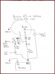
Please excuse the very rough wiring diagram attached.
 

Attachments

  • Bosch.pdf
    25.9 KB · Views: 740
Tips when hunting for your alternator in Pick a Part etc.

Many of the cars will have the original alternator. It's a weird thing, sort of a metal 'basket weave' design. Try and find one that has had a newer one fitted (Mitsubishi or Bosch usually). The newer ones will put out more amps, will have done less miles, and the bearings will be newer.

Years ago I put a Bosch alternator (with built in reg) on my old 404 and it thought it was Christmas to have real power running though its wire!

Dave
 
When you harvest the alternator also get the twin pin plug , same a injector plug.

Steps to wiring:

1) Disconnect the battery

2) Remove the existing regulator and join the lead from the battery to the heavy lead to old dynamo

3) Hopefully you have a 12v+v ignition switched at the regulator and spare wire going to the old dynamo. Connect a 2 watt light globe between these two wires. It easiest mount it in the engine bay.

4) At the old dynamo position you will one heavy cable. This goes to the big terminal (output) on the back of the alternator.
You will have the wire that goes to the light globe this goes to the "L" (or I) terminal in the two plug on the alternator

Hey thanks for the tip, I reckon I can figure all that out. I assume the 2 watt globe is a ballast resistor what happens if it blows?...BTW cute dog.
 
Tips when hunting for your alternator in Pick a Part etc.

Many of the cars will have the original alternator. It's a weird thing, sort of a metal 'basket weave' design. Try and find one that has had a newer one fitted (Mitsubishi or Bosch usually). The newer ones will put out more amps, will have done less miles, and the bearings will be newer.

Years ago I put a Bosch alternator (with built in reg) on my old 404 and it thought it was Christmas to have real power running though its wire!

Dave

Thanks for the tip
Graham
 
Tips when hunting for your alternator in Pick a Part etc.

Many of the cars will have the original alternator. It's a weird thing, sort of a metal 'basket weave' design. Try and find one that has had a newer one fitted (Mitsubishi or Bosch usually). The newer ones will put out more amps, will have done less miles, and the bearings will be newer.

Years ago I put a Bosch alternator (with built in reg) on my old 404 and it thought it was Christmas to have real power running though its wire!

Dave

Actually Dave

The new "squat" (compact claw) style alternator don't put out more "amps" per size of machine. There are some really big compact diode alternators around Mitsu Verada variants for example. They are a 120 amp machine. They are difficult to mount and because of the large diameter. They are not designed to incorporate "swing" type belt tensioning. Anyway you won't be driving a 1.7 kilowatt machine off a single vee belt.

Their main advantage is the RPM output characteristic. Let's compare :

A compact claw alternator (squat) off a Holden Vectra model KC 14v 40/70

A claw pole alternator (conventional) off a Holden VT model K1 14V 14/85

The Compact claw alternator delivers 40 amps at a shaft speed of 1500 RPM, however the Claw pole only delivers 14 amps

Thus the former alternator is more suitable for vehicles with high idle load devices like aircon and engine electric fans.

cheers


Robert
 
Normally the 2 watt lamp is a 2 w lamp is a 2w lamp. There are no shunt resistors. It the lamp fails tough!

The purpose of the lamp is a charge indicator. If the lamp lights the alternator is not charging. It should be on when the engine is stopped and go out completely when running. In the earlier electromechanical regulators the lamp was used to current limit the field circuit. No so with electronic regulators the lamp is strictly an indicator, but is required because it also supplies the field exciter current.

The dog, Max, is a Jack Russell broken coat. We adopted him from an animal rescue centre 7 years ago; when our last dog, a Fox Terrier, with a water and door fetish prone to uncontrollable barking frenzies was euthanised because of kidney failure.

Great little dog, smart, alert and very single minded and much more amenable than the Foxy.
 
Last edited:
Firstly, Rob that is a great looking little fella! (dog). Great breed too, lotsa fun!!

Secondly, I seem to remember a fellow frogger writing an article on such a conversion...

...oh, that would be me!! :tongue:

Most of the substantial info (even stuff that I couldn't find before my experience) has been covered here, but I'll check my old hard drive (new confuser since then) and see if I can contribute 'cause it all disappeared in the AF fire :(


:cheers: Binky.
 
Ducellier to Bosch

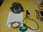
After nearly two years of putting it off I took the plunge and made the conversion from a Ducellier generator to a Bosch alternator harvested from a Mitsubishi magna.

Thanks to Robmac for the wiring diagram I was able to make up a suitable wiring harness to suit and the rest was easy.

The old Floride doesn't know what's happened with full power running through the system and everything (lights, blinkers etc) are just crisper and brighter. I've been monitoring the voltage and it gets to 13.8v so all looks well.

Thanks


attachment.php
 

Attachments

  • 003.jpg
    003.jpg
    37.1 KB · Views: 4,435
  • alter.JPG
    alter.JPG
    51.3 KB · Views: 16,017
After nearly two years of putting it off I took the plunge and made the conversion from a Ducellier generator to a Bosch alternator harvested from a Mitsubishi magna.

Thanks to Robmac for the wiring diagram I was able to make up a suitable wiring harness to suit and the rest was easy.

The old Floride doesn't know what's happened with full power running through the system and everything (lights, blinkers etc) are just crisper and brighter. I've been monitoring the voltage and it gets to 13.8v so all looks well.

Thanks


attachment.php

No worries. Until the project is undertaken, independently from the circuit there is no confirmation that all is correct.

Now it's built and working it we have confirmation the the circuit is correct.

The Bosch Holden alternators are bullet proof save the occasional regulator failure. Both brushes and regulator are cheap and usually replaceable with the alternator on the car. At $30 ea from a DIY auto recycler it's probably cheap enough to buy two and have a spare.

At 80 amp output the alternator more than copes with the increased load of modern auto accessories. The higher voltage makes everything work better as well.

Now all you need is some relays on the headlights and length of 10mm square cable from the alternator output terminal to the relay feed. Or the battery if in the front a cable from that. A single conductor from some circular orange electrical cable is ideal.

Just to confirm, the "S" terminal must goes straight to the battery, via a relay, 1^2mm cable is fine, this ensures that the alternator adjusts the o/p voltage to compensate from resistance in charging cable from the battery to the alternator output.

Yeah done all that....I rigged up an electric motor to spin the alternator and bench tested the whole apparatus and checked voltages etc. before I installed it in the car. Now it is installed I have a multimeter hooked up via the cigarette lighter socket so I can monitor what is going on as I drive.

Grinning like a split melon here,..... many thanks Robmac.

BTW why do I need a relay hooked up to the head lights?

Graham
 
Last edited:
I did a conversion on my 504. Original Bosch 35 amp to a Bosch with extra amps and built in regulator. [Can't recall the output ex Toyota Corolla].
Wiring it up was simple, used existing wiring except for one redundant wire that came from the external regulator which was tucked into the wiring harness.
Some initial concern that the dash voltmeter never read higher than half way, battery voltage to spec. Told by sparkie that it will be OK.

The previous posts re converting seemed over complicated to me. But what do I know?:wink2:
 
BTW why do I need a relay hooked up to the head lights?

Graham

robmac will give you the tech answer but,

Running your headlights through a relay will give you the full umph available from your new set-up (brighter lights) and take the heat off your switches.

Cheers
Chris
 
Now all you need is some relays on the headlights and length of 10mm square cable from the alternator output terminal to the relay feed. Or the battery if in the front a cable from that. A single conductor from some circular orange electrical cable is ideal.

Send the apprentice out to purchase the square cable :)

You might find this old post useful regarding the headlight relay idea.
http://www.aussiefrogs.com/forum/showthread.php?88767-Saving-the-DS-light-switch&highlight=

And this is a kit to do the job:
http://www.ebay.com.au/itm/H4-9003-...r_Truck_Parts_Accessories&hash=item2a169de78b
 
I did a conversion on my 504. Original Bosch 35 amp to a Bosch with extra amps and built in regulator. [Can't recall the output ex Toyota Corolla].
Wiring it up was simple, used existing wiring except for one redundant wire that came from the external regulator which was tucked into the wiring harness.
Some initial concern that the dash voltmeter never read higher than half way, battery voltage to spec. Told by sparkie that it will be OK.

The previous posts re converting seemed over complicated to me. But what do I know?:wink2:

I'll answer two questions.
------------------------------------------------------------------------------------------------------------------
Wildy,

Yes it's more complicated than days-gone-by alternators with external regulators. But the convenience of using a Holden alternator with parts available at a "milk bar" has it's advantages. Plus the fact they are in plentiful supply and are likely to be for a long time.

Another benefit is the "s" (sense) facility. This feature maintains the voltage at the battery at exactly the correct charging voltage independent of current load and voltage drop in the alternator output to battery cable.

As the internals of the alternator heat up, the copper stator windings and the rectifier diodes the voltage drop increases. Sensing the battery terminal voltage allows for these losses to compensated for as well.

---------------------------------------------------------------------------

Graham,

Headlights need relays for a similar reason: voltage drop.

The traditional set up is to switch the headlights through a dash or column mounted switch. If you consider the length of cable between battery,switch and headlight globe there can be quite a few meters. Manufacturers use the minimum size cable they can get away with. When the car was designed it probably had 40/50 watt globes. These days 50/60w QI lamps are standard. So the wiring is now handling more current than the original design spec. Plus the fact the contacts on the switches are getting on in years and have a higher resistance than when new.

Take the cable length, high resistance contacts etc etc in consideration you "loose" a few volts in the wiring and switches and end up 10 volts at the head lamp globes. This reduces the brightness.

So the answer is to fit relays to LB and HB and run heavy wiring from the battery or alternator to the relay input. And to run heavy wiring to the lamps. Also make sure the earth for the lamps is on the chassis directly not a mudguard. Locate the relay as close to the lamps as possible and use the existing headlight wiring to trigger the relay coil. A relay is a remote switch, the coil closes another "set of contacts".

Your are effectively moving the dash switch to where the relay is located and reducing the length of wire in the headlamp circuit. This means the headlights get full system voltage applied to them and are brighter. The dash/column switch only triggers the relay coil, a load of around 8 watts so the switch contacts last longer.
 
Send the apprentice out to purchase the square cable :)

You might find this old post useful regarding the headlight relay idea.
http://www.aussiefrogs.com/forum/showthread.php?88767-Saving-the-DS-light-switch&highlight=

And this is a kit to do the job:
http://www.ebay.com.au/itm/H4-9003-...r_Truck_Parts_Accessories&hash=item2a169de78b


I'm far too stingy for that, relays at wreckers and indeed wiring looms with relays sockets and lots heavy wiring are a few bucks at DIY wreckers.

If you can't get value for your money harvest all the wiring and relays/sockets you need and tape it into a single loom before you take it out.

Most wreckers sell a loom or half loom for $15 so you can customise a loom for your needs and price :D

You will note I changed my cable terminology to 10mm ^2 to avoid confusing the non technical.
 
Last edited:
Graham, the other really compelling reason for fitting relays is to protect the original headlight switch. Running all the current for the headlights, especially if the globes have been up-rated, risks cooking the old original switch or even starting a fire. If there is a little corrosion or other muck in the switch the higher resistance can mean the switch gets far too hot. The same applies to various aging connectors and wiring, especially out of sight behind the dash board.

Once the relays are fitted the power through the original wiring drops dramatically. Of course the brighter headlights are a great bonus too :)
 
I'm on it guys...I'm always looking for things to do and ways to improve my ride and relays on the headlights sound like the way to go.

I drove the Floride tonight and came home very happy with the brighter lights...:)
 
Top