
You are using an out of date browser. It may not display this or other websites correctly.
You should upgrade or use an alternative browser.
You should upgrade or use an alternative browser.
gererator to alternator conversion.......
- Thread starter 56 Fregate
- Start date
Hi Graham,
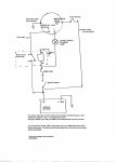
Here is the sketch.
Just a few notes:
The cable sizes specified are auto cable sizes not electrical cable sizes.
Locate the relay as closes as possible to the headlights, preferably equidistant from both. I would suggest new connectors be purchased for the headlight globes.
Make sure the the earths for the headlights are connected to a secure chassis grond , or at least a welded on body panel. Not on to a bolted mudguard of similar.
VT commodores are a good source of relays, sockets, fuses and cable. There is a fuse/relay box just inside the driver side bonnet area at the front.
This company has anything and everything auto electrical and are reasonably priced. They will ship to you.
http://www.jaydeeautocables.com.au/catalogue/Jaydee_Catalogue.pdf
Any questions, just ask.
cheers
Robert.
Attachments
Thanks for the design Robert.
I've been thinking overnight how this 53 year old car could benefit from not only having better/brighter lights but more importantly taking the pressure off the old switches and wiring etc.
I have a couple more weeks off work so will get started with the upgrade next week.
Thanks again for sharing the knowledge.
Graham
Running all the current for the headlights, especially if the globes have been up-rated, risks cooking the old original switch or even starting a fire. If there is a little corrosion or other muck in the switch the higher resistance can mean the switch gets far too hot.
In a Traction Avant that's the only reliable source of heating. The great thing is that the switch is a solid lump of brass, so it stays warm for ever, super for frosty mornings. It's even better than normal TAs, too: I have a 6v altenator so there is enough current to heat the switch and have headlights on.
")
I've attached the service manual link for the specified Alternator to add value to the thread and provide service reference info
http://apps.bosch.com.au/AAExtranet_TechSearch/docs/repairinstruction/altR11-0.pdf
Happy days
Could a mod please correct the spelling in thread title (no offence intended G) it will make the thread easier to find when using " google in house" search.
Whoops may not be such a good idea it will unlink all posts pointing to this thread.
As you were.
Last edited:
I've tried to fix that spelling error many times but it doesn't want to be fixed..
Only a mod can change it. Because the forum database uses the thread title as "key" indexing field. Changing it may cause Database corruption.
It will also stuff up any links pointing to the thread.
So your typo is there for AF posterity.
It will also stuff up any links pointing to the thread.
So your typo is there for AF posterity.
Alternators again..
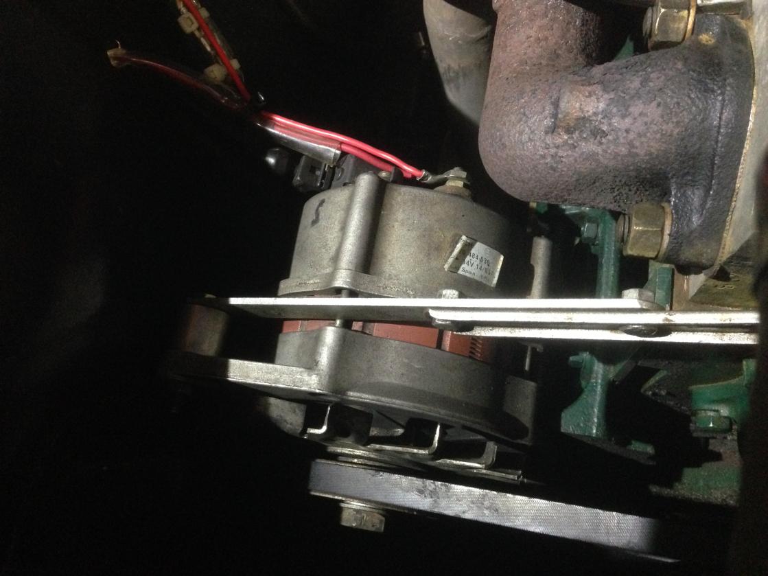
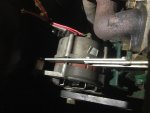
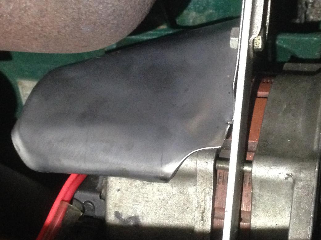
I consider that my Bosch alternator is too close to the exhaust header and I'm concerned about radiant heat melting the internal wiring or worse. I only have about 30mm gap.
The obvious fix would be to place a steel or aluminium shield between the two to take most of the heat away.
Is this something anyone else has done...?
Attachments
Last edited:
Cut strip off the fire blanket at work and use some silicon and rivets to stick to a piece of aluminium.
Worked for me.
Worked for me.
Hmm good thought but my conscience wouldn't let me tamper with a piece of fire safety equipment. Some old asbestos brake lining would be much more conducive to good health and safety methink.
A strip off the "rear" end and lovingly refolded and replaced doesn't imply tampering.
This mob have a foil coated high temperature material
http://www.colan.com.au/media/wysiwyg/Downloads/Thermal_Catalogue.pdf
Personally I'd do a search at a diy wrecker in the BMW or Ovlov section and look for something there.
Small quantities of exotic materials can be very expensive and hard to get from big suppliers.
Here is another source, but mainly sleeving it seems
www.techflex.com.au/techflex-braided-sleeving-products/insultherm-tru-fit-braided-sleeving

Meh! That should help, there isn't any insulation yet just a steel plate, I'll see how that goes.
Some this thermal blanket would be the go... Custom Thermal Insulation Blankets | Manifold Exhaust System Insulation
Here is an updated and more legible schematic drawing for the conversion.
Two changes:
Reversed the relay coil numbers on the diagram to reflect current polarity conventions.
Added a fuse to the main charging output on alternator, to comply with current good practice.
I won't bother making any changes if you have one currently installed.
On the behest of Pug 72 I've amended the drawing to add the "missing" fuse''
Attachments
Last edited:
Hi Robmac
On the old drawing you had a fuse between the +ve terminal to the relay point 87. Is this fuse now redundant?
it's belt and braces. Good practice says to fuse anything connected lead acid accumulator because of extremely high short circuit current.
If I've left it out of the "new" circuit I. l I guess I need to revise it again. Thanks for pointing out my error.
Meh! That should help, there isn't any insulation yet just a steel plate, I'll see how that goes.
You need it to be a sheet of polished aluminium with an air gap alternator side. Aluminium (especially polished) has a very low emissivity of heat. To see what I mean, grab a sheet of polished aluminium and heat it with a small gas torch. Get it good and hot ..... turn the heat off and put your hand near it ..... Doesn't feel hot right ?? DO NOT TOUCH IT. It will be VERY hot, but it is poor at emmiting this heat. So whatever is the other side of your polished aluminium heat shield should not get as hot. This is why the foil based insulators are so good ( the two layers of foil have low emissivity of heat ... and the filler between them is the air gap).
seeya,
Shane L.
Yes, good point re the aluminium and air gap.
I just covered a 2000km road trip with the above arrangement and nothing melted, which was probably just good luck. I'll have a look at an aluminium equivalent. I doubt that I could replicate the high school type hand beaten objet d'art of the steel one and might need to resort to a more 1980s squarish design, but there you go, more tinkerage coming up.
I just covered a 2000km road trip with the above arrangement and nothing melted, which was probably just good luck. I'll have a look at an aluminium equivalent. I doubt that I could replicate the high school type hand beaten objet d'art of the steel one and might need to resort to a more 1980s squarish design, but there you go, more tinkerage coming up.
Why not wrap the exhaust with the material available from cheap motor factors? It may not win you any race, but it will help with heat control. Or if you're rich, ceramic coating on the exhaust.
Why not wrap the exhaust with the material available from cheap motor factors? It may not win you any race, but it will help with heat control. Or if you're rich, ceramic coating on the exhaust.
Thanks for the suggestion Schiltzy but I prefer the old school look over the new fangled, poncey look.