Well observed. The early photos above were missing the later idler pulley addition, at that time I was mainly concerned about getting the alignment correct.May want to consider that a drive belt needs 120 deg wrap to work correctly.
The power steering pulley does not have this and will slip.
One of many
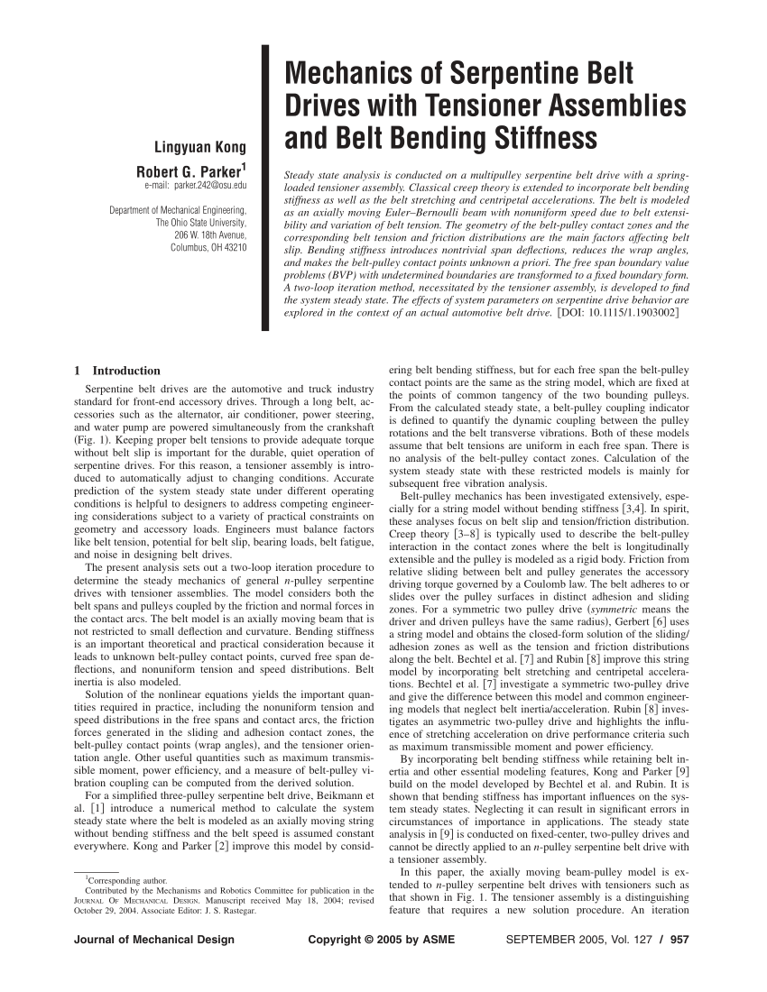
The Ultimate Guide to Belt Drive: Maximizing Efficiency and Performance | MachineMFG
Discover how to optimize belt drives for maximum efficiency and performance in this comprehensive guide.www.machinemfg.com
The higher the load the more angle of contact is required
One tensioner per belt otherwise the belt will oscillate badly on two
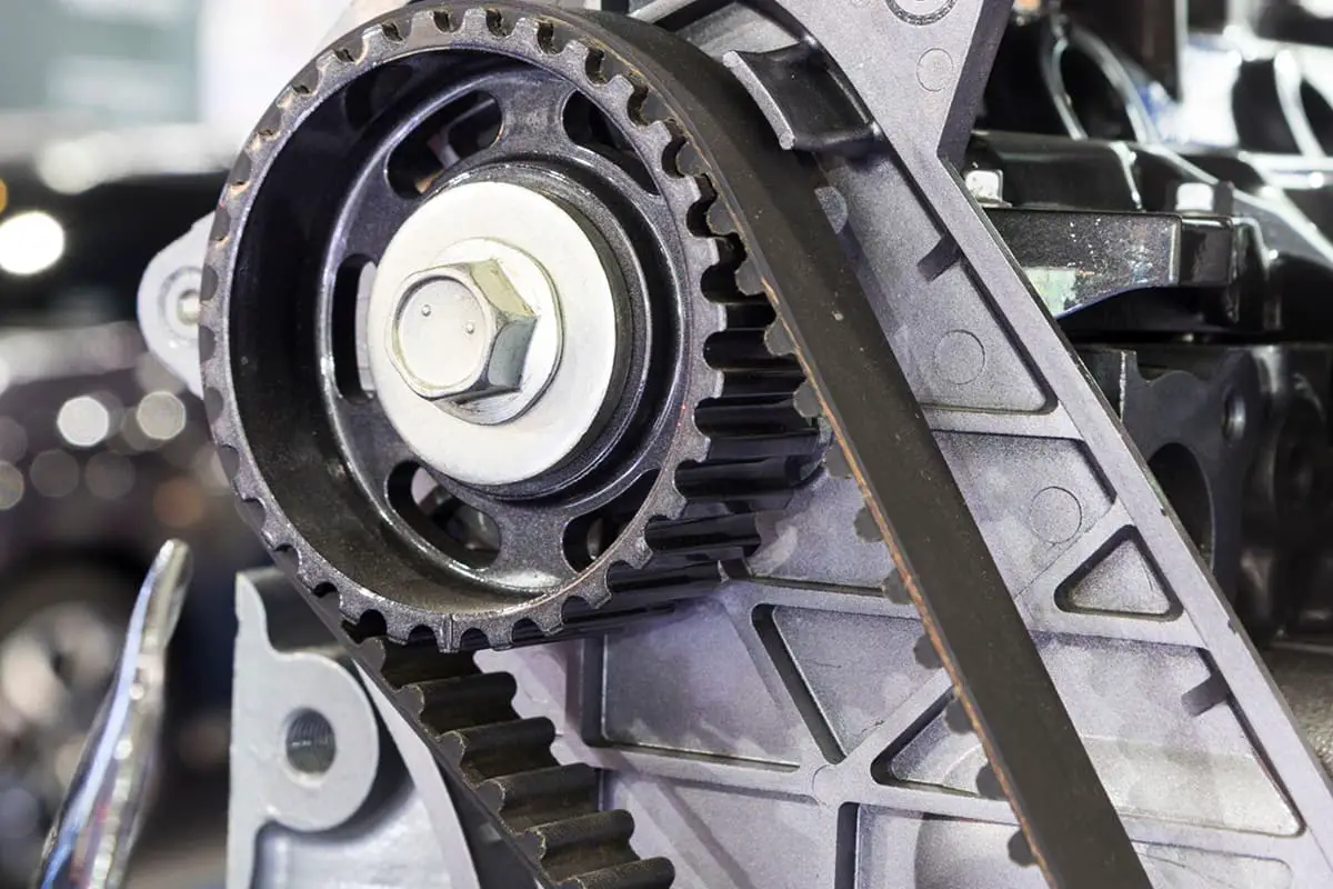
View attachment 238877
I'm yet to build the tensioner (it will be higher up, underneath the air conditioning compressor), but the angles of the belt shown in this photo will be pretty close.
My biggest concern is a fairly long stretch of unsupported belt between the crank and the air conditioning compressor. If it flaps, I may have to add an additional idler.