Rule of thumb to determine tappet clearance

Rally

Active member
Fellow Frogger
Joined
Nov 1, 2010
Messages
737
Location
Pearl Beach NSW
I have just rebuilt my PRV 2995 cc V6 , useing a high lift long duration cam shaft , I set the tappets at the recommended clearance of .014 ( by the supplier of the cam ) , these setting result in a lot of tappet noise.
My question , is there a rule of thumb to calculate a suitable clearance based on valve size , length of valve stem , ramp angles etc that will be quiter but not harm the valves or rob me of too much horse power .
What are the pit falls in reducing the clearance too much ?
 
Depejnds on the grind of the cam. Alconi road cams are 0.4mm (0.016") and they are quiet. And whether the cam grind was meant for the motor.
 
i agree with peter T ,the only other thing i could think of is to check the clearance with the engine hot i realise this could be difficult as covers need to be removed etc ,i cant see how the valve grind would have anything to do with the ,valve gap as its the back or the cam thats against the valve gear when on compression ,valves not activated ,how do manufacturers specs compare to what you have now ,
 
MAYBE THANOS WOULD BE YOUR MAN ,RUNS AN EX WORKS 504 COUP V6 IN GREECE SOMEWHERE ,
 
I have just rebuilt my PRV 2995 cc V6 , useing a high lift long duration cam shaft , I set the tappets at the recommended clearance of .014 ( by the supplier of the cam ) , these setting result in a lot of tappet noise.
My question , is there a rule of thumb to calculate a suitable clearance based on valve size , length of valve stem , ramp angles etc that will be quiter but not harm the valves or rob me of too much horse power .
What are the pit falls in reducing the clearance too much ?
Is that an Imperial 14 thou? Wow.....
 
That's very loose if on the inlet. I've never seen a formula, but it would be based on the thermal expansion of the valve & material. ie a longer valve needs more clearance, as it will grow more. Exhaust needs more than inlet, as they get hotter and thus grow more. I would set the inlet at 0.008-0.010" and the exhaust 0.012-0.013".

Insufficient clearance on the inlet will result in loss of compression. Insufficient on the exhaust will burn out the valve, in addition to loss of compression.
What about thermal expansion of the cylinder head? That would close up the clearances.
 
Depejnds on the grind of the cam. Alconi road cams are 0.4mm (0.016") and they are quiet. And whether the cam grind was meant for the motor.
Hello, real information! Good idea. :) I'd never have thought such a clearance would be quiet, but I guess the cam profile is the answer to that question.
 
Hi :)
The clearance depends on the cam grind because of the "quietening ramps" on the start and finish of the lift(and the other factors mentioned too). All road cams have them for the very obvious reason. But back in the ol'days motor bike cams often did not and were very rattly. Probably wore out faster also. I recall doing a dial gauge cam lift graph on a couple of Triumph cams to see what it was about. If you set 0" clearance you can see the small initial lift to take up the clearance, then the real lift starts much faster. Same at the other end ! :rolleyes: This is also why you set a big clearance for 'checking the timing'. :oops:
So If you wanted to try you could use a small feeler when idleing and see what that does to the noise. After all the very old Holden motors and similar had the tappets set hot and running with a long feeler strip and the adjusting screw going up and down. :cool:;)Fun !!! You could find the loose noisy ones easy enough with the feeler as it pulled it(slightly) into the gap. 0.008" and 0.010" was the standard. Those engines were not my favourites but I did some as they were common and paid the bills. :unsure:
https://v-tec.velocette.info/Cam_dynamics.html
From that site. You can clearly see the ramps. Jaahn
1610914979168.png
 
Last edited:
  • Like
Reactions: COL
Hi,

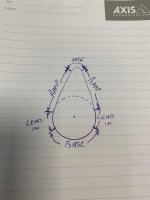
Having Patented a 3D Variable cam in 1993/4, I have learnt quite a lot about cams. Theoretically you cannot set the clearances by Rule of Thumb, but I can't see any bad about not doing so.

There are various namings of the phases of a cam lobe and the ones I used at the time is the ones on the rough sketch I made. The cam grinder will tell you the valve clearance based on the "Lead in". That is the gap/distance from the "Base" end to the beginning of the "Ramp" so that the valve clearance is taken up slowly before the ramp or acceleration starts. If there wasn't a lead in and the ramp started straight away you would have had a "hammer" effect everytime the lift cycle starts.

The same happens for the closing of the valve. The opposite lead in let the valve seat gently in the closed position. Again, if it wasn't there the valve would have slammed itself on the seat like a hammer shot and I don't think it would take long before the head breakes off and causes a piston damage that is only good for a conversation starter on the coffee table.

Frans.
 

Attachments

  • CamProfile..jpg
    CamProfile..jpg
    149.2 KB · Views: 148
Top