Sorry. I was just pointing out that replacement pumps seem to assume that they will be fitted over 9mm studs, whereas my 1968 car has 8mm studs. Upshot of this is that there is potential for shear movement due to the pull of the pulley - and water leaks. With an efi being a later car, you studs probably are 9mm and you don't need to worry about it.

You are using an out of date browser. It may not display this or other websites correctly.
You should upgrade or use an alternative browser.
You should upgrade or use an alternative browser.
Resurrecting a Goddess.......Twice
- Thread starter faulksy
- Start date
Does your DS have the hydraulic gear shift? Mum sold her DS21 about 30 yrs ago, the young guy only wanted the ECU but we told him the whole car or nothing. Our car had hydraulic gear change. The autos and hydraulic shift versions had the gear lever pointing to the right side.Episode 3: The Woes of Bosch D-Jetronic Fuel Injection
The Bosch D-jet system at it's core is very simple, It uses a vacuum and temperature sensors to determine engine conditions and uses a set of dual points to fire the injectors in banks of 2 (1+3 & 2+4).
It's biggest problem these days is availability of parts and the generally non repairable nature of the units. Bosch never intended for them to be opened and repaired regarding them as throw away items. Nice idea in 1970 when you could get parts but very unhelpful 50 years on. The whole troubleshooting checklist is really a set of pass fail checks. When a unit fails you replace it, simple haha. As a general, there isn't a lot of info out there in english let alone specific to the DS.
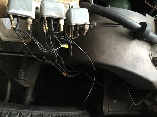
The first port of call was to check the computer was getting power. The easiest way to do this is turn the key in the ignition. 2 things should happen, the main power relay should trip, and the fuel pump should run for approx. 2 seconds. The relays live on the side of the battery frame and are jammed against the wing. Its far easier to remove the wing so you can see what youre doing. As a general early EFI cars have 3 relays and late ones have 2. The cold start relay is deleted on later cars. With that said, from left to right we have main power, fuel pump and cold start/impulse relay.
Turning the key revealed we had power so next was to go through the wiring sensor by sensor to see what was what. Whilst you can just take the connector off each sensor the better option is to unplug the ECU and measure everything from the multi-pin connector. This kills two birds at once, it checks the sensor and all of the wiring to it. On this model the ECU lives in the passenger footwell under a false floor. I believe later cars have it counted under the dashboard. Each wire shoudl have a cloth tag with a number on it but on mine they had all been lost to the ages. Pin 1 is the furthest from where the wires enter the case.
Rather that spell out the testing procedure, the best place to go is the technical notes otherwise known as Citroen Manual 586/5 and the Citron fuel injection manual. Let me know if anyone wants a blow by blow of how to test the EFI system or a link to the documents.
Going through the system wire by wire a grand total of 4 times, revealed that all the wiring was fine and the sensors were within spec. GOing through the checklist resulted in a car that would start but stall after a few seconds. The main injectors just weren't firing. The first time it fired, it shot forward causing me to stamp on the breaks. This did two things, stalled the engine and seized the breaks on. I ended up testing everything 4 times because twice just didn't seem enough haha. Also, with the system refusing to run I figured something had to be wrong with a sensor as everyone told me repeatedly that the ECUs never, ever break.............

Throwing caution to the wind and against all advice I had a closer look at the ECU. Punching the part number into the Bosch parts database revealed that this part was intended for a 1973ish DS23. That was the first red flag. The next was the words DS safari handwritten on the casing. Out of curiosity i took the cover off and discovered a solid inch of mud inside it and the wires to the resistor bank totally rusted through. Without the test bench to tune the ECU it really isn't worth trying to repair them. Bosch used military grade components with less than 1% tolerance and each unit was hand tuned at the factory. The hunt was now on for a new ECU. They can be had out of Europe for anything upwards of 500 EUR with no guarantee they work. The ECU and the MAP sensor are matched insofar as a 0280150011 MAP goes with a 0280000011 ECU. Mixing and matching will work but your results may vary. Asking around the car clubs turned up exactly the right ECU that had been removed from a car some 30years ago and had been on a shelf since. After a trip to pick up the new ECU it was swiftly installed. Not really expecting much the key was turned and the starter given a prod. To mine and my Dad's amazement this happened.
Suddenly the car had gone from a from a conceptual art installation to viable transport!
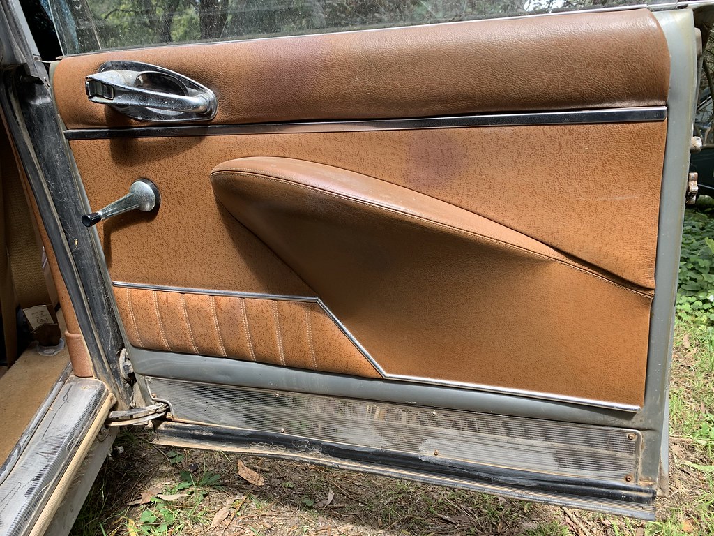
Now for a job that shouldn't have needed doing. You may recall a couple of weeks back I mentioned the corner of one door card was smashed making it impossible to fit all the clips. It held on long enough to survive concours but I ended up taking it off as it fell off overtime the door was opened.
Unlike the original, these new one use a thin piece of plywood as the backing. The arm rest is also riveted on instead of being held in place with a thousand staples.

The damage was to the bottom corners with the rear (right in photo) being the worst.


Unpicking the 50 or so staples that secure the leather revealed the full scale of the problem.
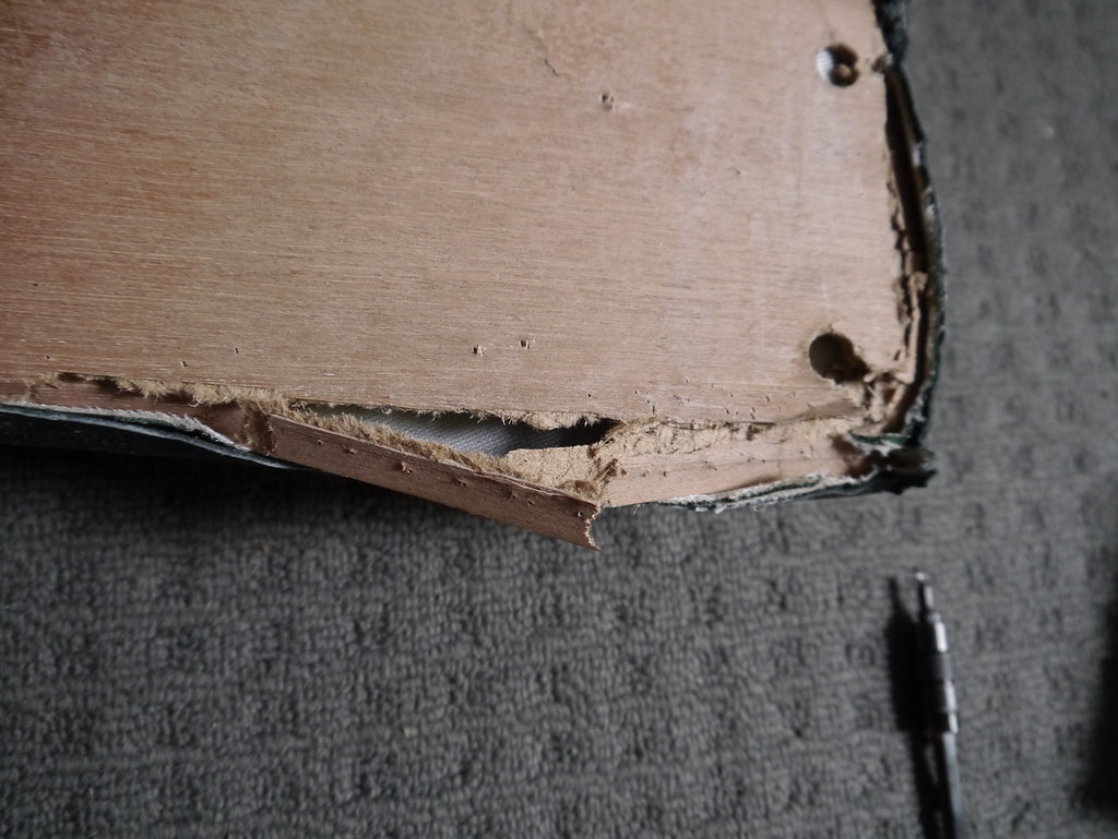

When I fitted them 2 months ago, it was the first time they had been out of the shipping crate since arriving. They were really well packaged with no damage to the crate. I can only guess it was dropped at the factory. The sheer number of staples must have weakened the plywood as it split almost exactly along that line.
I've still got the old singed doorcards and had considered just swapping the new leather onto one of the old backings. After taking out just these few staples, it became clear how tedious that operation would be for not much gain. So, plan B
I had some offcuts of thin polycarbonate sheet left over from building architectural models which seemed like a good way to reinforce what was left and rebuild the broken corner.
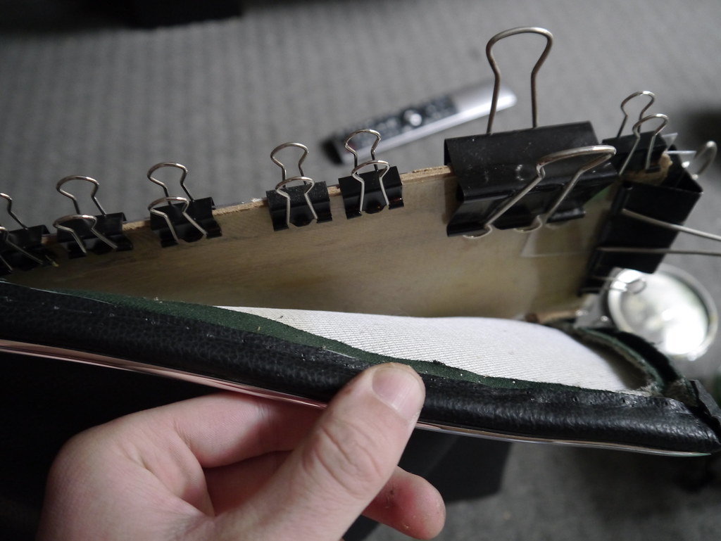

It was left like that for a day before removing the clips. Whoever invented bulldog clips needs more recognition, they are brilliant things!
Whilst my staple gun will put staples through the polycarb sheet, it seemed a shame to spend all this time rebuilding only to smash it apart again. Instead I opted to glue the leather back into place.

The clip had to be opened up a touch because of the added thickness but that's a minor price to pay. So far the door card is staying in place just fine.
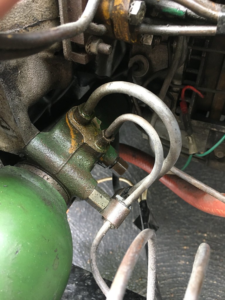
While mucking about I noticed a pretty consistent drip of LHM from under the gearbox. Turn out the main pressure line to the regulator had loosened itself and was weeping. An easy fix with a flare nut spanner.
Now I just have to work out why the passenger side door catches are so temperamental. One day they open and close with ease, the next day you have to slam the hell out of them to get them closed. The driver's side is perfect.
Unlike the original, these new one use a thin piece of plywood as the backing. The arm rest is also riveted on instead of being held in place with a thousand staples.
The damage was to the bottom corners with the rear (right in photo) being the worst.
Unpicking the 50 or so staples that secure the leather revealed the full scale of the problem.
When I fitted them 2 months ago, it was the first time they had been out of the shipping crate since arriving. They were really well packaged with no damage to the crate. I can only guess it was dropped at the factory. The sheer number of staples must have weakened the plywood as it split almost exactly along that line.
I've still got the old singed doorcards and had considered just swapping the new leather onto one of the old backings. After taking out just these few staples, it became clear how tedious that operation would be for not much gain. So, plan B
I had some offcuts of thin polycarbonate sheet left over from building architectural models which seemed like a good way to reinforce what was left and rebuild the broken corner.
It was left like that for a day before removing the clips. Whoever invented bulldog clips needs more recognition, they are brilliant things!
Whilst my staple gun will put staples through the polycarb sheet, it seemed a shame to spend all this time rebuilding only to smash it apart again. Instead I opted to glue the leather back into place.
The clip had to be opened up a touch because of the added thickness but that's a minor price to pay. So far the door card is staying in place just fine.
While mucking about I noticed a pretty consistent drip of LHM from under the gearbox. Turn out the main pressure line to the regulator had loosened itself and was weeping. An easy fix with a flare nut spanner.
Now I just have to work out why the passenger side door catches are so temperamental. One day they open and close with ease, the next day you have to slam the hell out of them to get them closed. The driver's side is perfect.
Yet more stuffing around with shims, and strike plates has yielded a result on the passenger side doors. I ended up adding a shim to the top and bottom hinge of the rear door to bring it out from the frame. This gave just enough extra adjustment on the stike plate to now work properly.
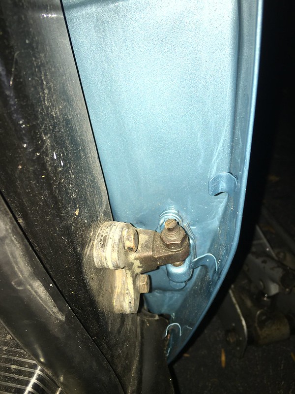
The front door needed special treatment. The front wing had to come off to get at the hinge bolts and then the whole door needed to be rotated relative to the frame opening. The net result is that all doors are fully functional again!
With that done, the car went back to the paint shop to have a few things touched up which necessitated taking the door cards off for protection. They needed to come off anyway to glue the vinyl protection pieces on.

Before they went on, each door got a good blasting of Valvolene Tectyl cavity wax inside around the seams and all along the bottom. With a bit of luck the doors wont rust again in my ownership.

The door cards went back on very easily although the particle board backing won't survive them being taken off again.

I also finally got around to fitting the pallas kick plates after agonising for way to long over whether to use pan head or raised countersunk screws. Citroen used both types in different places so both are valid options. A mates barn find 69 pallas provided a good reference photo which swung the vote in favour of pan head. I think the details are finally getting to me........
Full of enthusiasm to fit the last of the trim I dug out the bag of little red clips and set about inserting them into the bottom edge of the panels.

Each hole got a smear of grease for protection. The clips themselves are easy enough to insert. The driver's side went well however it appears that the panel shop didn't drill the holes on the passenger side. I may have to resort to double sided tape after all. What are peoples experience with using tape to hold the lower and mid trim on?
The front door needed special treatment. The front wing had to come off to get at the hinge bolts and then the whole door needed to be rotated relative to the frame opening. The net result is that all doors are fully functional again!
With that done, the car went back to the paint shop to have a few things touched up which necessitated taking the door cards off for protection. They needed to come off anyway to glue the vinyl protection pieces on.
Before they went on, each door got a good blasting of Valvolene Tectyl cavity wax inside around the seams and all along the bottom. With a bit of luck the doors wont rust again in my ownership.
The door cards went back on very easily although the particle board backing won't survive them being taken off again.
I also finally got around to fitting the pallas kick plates after agonising for way to long over whether to use pan head or raised countersunk screws. Citroen used both types in different places so both are valid options. A mates barn find 69 pallas provided a good reference photo which swung the vote in favour of pan head. I think the details are finally getting to me........
Full of enthusiasm to fit the last of the trim I dug out the bag of little red clips and set about inserting them into the bottom edge of the panels.
Each hole got a smear of grease for protection. The clips themselves are easy enough to insert. The driver's side went well however it appears that the panel shop didn't drill the holes on the passenger side. I may have to resort to double sided tape after all. What are peoples experience with using tape to hold the lower and mid trim on?
Get the auto type double sided tape from serious shops and you won't have a problem. Not sure who makes it or what the branding name is but it is good enough to be used by manufacturers themselves these days. It's exxy.
I would not longer bother with fiddly fixings like the inserts, screws etc. That tape is much better. You just need to make sure the ornament follows the panel contour otherwise if there's any tension on the tape it will eventually come off.
I would not longer bother with fiddly fixings like the inserts, screws etc. That tape is much better. You just need to make sure the ornament follows the panel contour otherwise if there's any tension on the tape it will eventually come off.
Time for a small update.
The car has been running well although does seem to be drinking fuel at an alarming rate! Somewhere in the region of 25L/100km if the odometer is to be believed. I've lowered the fuel pressure from 30psi to 28psi which has made a difference to idle smoothness and general running. Hopefully it will translate into an increase in economy.
In other news, I've finally gotten around to fitting the sun visors. The brackets needed masking up and a coat of satin black. The effect is quite striking between the shiny chrome and deep black.


There is a series of different washers that go onto the visor arm. The black one sits between the bracket and the arm while the other two go on the backside between the bracket and castellated nut.

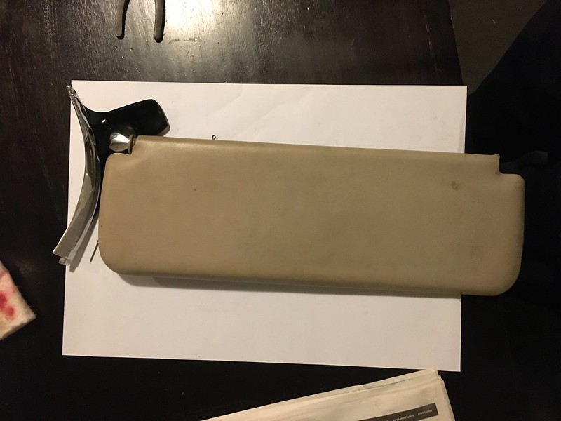 It's a fine adjustment of the nut to create enough clamping force to keep the vision in place. Installation required some screws to be painted black. Getting everything lined up with the speednuts in the frame is a bit awkward.


It also decided to register it's displesure at not moving for 3 weeks bu spontaneously springing a coolant leak. Everything looked fine form on top and getting underneath wasn't an option. So off with the alternator which revealed a cracked lower hose.
There is a hose off a Jaguar XK which would fit but nobody has stock locally so the original hose was patched as a temporary fix.

I must have given a return a bit to much of a shove as no sooner had the coolant leak been fixed, a stream of LHM appeared from under the car. I've tightened a hose clamp on what I suspect is the offending hose and it appears to have stemmed the flow, time will tell.
The final lockdown project has been to cleanup the hydraulic pump that went through the fire. It sat full of water for a month or two and the results aren't pretty.

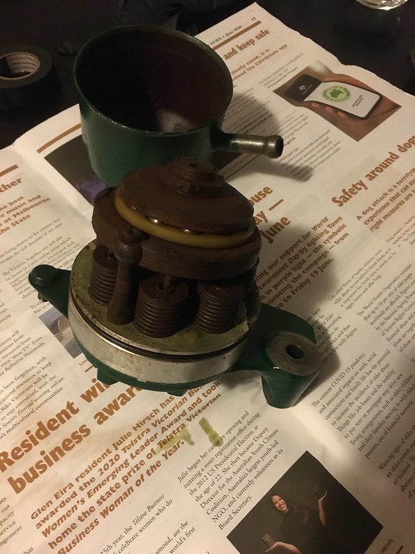

All 7 pistons were jammed at the bottom of their stroke. It took a hammer and drift to get them out.


The pump body looks fine after a good scrubbing with fine steel wool as do all the working parts. The bearings aren't seized but will need to come apart for cleaning. Each piston ended up needing a go with some 2000 grit wet and dry before they would slide into the cylinders. They all seem to have good compression so there is hope. Everything is now ready for reassembly.

It will need pressure testing before the casing is put back on. Aside from wanting to fix it up, my car's original pump leaks from the front bearing. This one was a brand new rebuild from Roger Parker that got swapped onto my car not long before the fire and didn't leak at all.
The car has been running well although does seem to be drinking fuel at an alarming rate! Somewhere in the region of 25L/100km if the odometer is to be believed. I've lowered the fuel pressure from 30psi to 28psi which has made a difference to idle smoothness and general running. Hopefully it will translate into an increase in economy.
In other news, I've finally gotten around to fitting the sun visors. The brackets needed masking up and a coat of satin black. The effect is quite striking between the shiny chrome and deep black.
There is a series of different washers that go onto the visor arm. The black one sits between the bracket and the arm while the other two go on the backside between the bracket and castellated nut.
It also decided to register it's displesure at not moving for 3 weeks bu spontaneously springing a coolant leak. Everything looked fine form on top and getting underneath wasn't an option. So off with the alternator which revealed a cracked lower hose.
There is a hose off a Jaguar XK which would fit but nobody has stock locally so the original hose was patched as a temporary fix.
I must have given a return a bit to much of a shove as no sooner had the coolant leak been fixed, a stream of LHM appeared from under the car. I've tightened a hose clamp on what I suspect is the offending hose and it appears to have stemmed the flow, time will tell.
The final lockdown project has been to cleanup the hydraulic pump that went through the fire. It sat full of water for a month or two and the results aren't pretty.
All 7 pistons were jammed at the bottom of their stroke. It took a hammer and drift to get them out.
The pump body looks fine after a good scrubbing with fine steel wool as do all the working parts. The bearings aren't seized but will need to come apart for cleaning. Each piston ended up needing a go with some 2000 grit wet and dry before they would slide into the cylinders. They all seem to have good compression so there is hope. Everything is now ready for reassembly.
It will need pressure testing before the casing is put back on. Aside from wanting to fix it up, my car's original pump leaks from the front bearing. This one was a brand new rebuild from Roger Parker that got swapped onto my car not long before the fire and didn't leak at all.
Nice work Faulksy. I would be interesting in seeing how that pump holds up given that you have had to sand the bores/ pistons - albeit it finely/ lightly.
Me to, I figured it can’t hurt to give it a go. I’ll take it over to the club’s testing rig and see how badly it leaks. I’m expecting at least one piston to leak as the sealing face for the valve disc has a big gouge across it.
The pressure test results are in! Cylinder 5 leaks very badly but the rest are good. Might have to swap out a piston assembly if the sealing face can't be salvaged.
On another note, yet another rear suspension boot has failed at the point where it folds back on itself. Getting decent quality spares seems to be neigh on impossible so I’m wondering if a front suspension boot or a CX one can be fitted. The concertina design seems far less prone to tearing.
On another note, yet another rear suspension boot has failed at the point where it folds back on itself. Getting decent quality spares seems to be neigh on impossible so I’m wondering if a front suspension boot or a CX one can be fitted. The concertina design seems far less prone to tearing.
Last edited:
Episode 21: Let there be light!
It's been a bit of a mission but 220m, yes you read that right, (750ft) of wire later and the car now has brand new wiring front to back. The final task was to make up the rear loom which completes almost a full lap of the car. Here it is laid out on the floor next to a GS!

Colour coding all the ends took ages, not helped by the fact I had aparently used two different wiring diagrams at some point and put the wrong colours on. The new bullets seem much more strudy than the original ones, time will tell...

Running the wiring in the sill is tedious to say the least. Access to the brackets is restricted by the bundle of hydraulic lines that also run down the passenger side. Now for the last great unknown.....Does it all work?
Connecting all the switches, lights and sensors up brought the warning lights to life so that was a good sign. However turning the headlight switch produced some very weird results. No matter which way it was turned, pushed and pulled a random combination of lights came on, even an indicator at one point! checking the grounds and other connections revealed everything to be in order and left me wondering how I'd managed to stuff it up that badly. Working on a hunch that the switch might be buggered I directly connected the switch outputs to +12 and to my surprise all the lights worked properly. Putting a meter across the switch proved it was not behaving so time to do some digging.
For those playing at home, black is +12, mauve is the parking lamps, green is low beam, yellow is high beam and red is the driving lamps. Without a relay for the high beams there would be 220W of power being drawn through the yellow wire! There is a reason I doubled the wire gauge for the headlights when building the new looms.
Drilling out the 4 brass rivets that hold the switch together released several springs and brass plates which all had to be picked up off the floor and accounted for. The switching action is achieved by rotating a brass plate across several contacts embedded in the back cover of the housing.
The square plastic part is what provides the notches. There is a small spring loaded pin on one side which is what activates the driving lamp switch.


The push switch for the driving lamps is very similar to the mechanism in a retractable pen.

It all looked brand new inside so I assumed something had gotten out of alignment. Reassembly is achieved through a careful balancing act requiring three hands. Not feeling overly confident the switch was plugged back in and amazingly worked perfectly! Even the indicators worked.


Feeling somewhat pleased, I decided to quit while ahead and call it a night. Next up, upholstery........
Someone in the UK with a third dash car has light switch problems. The unit on their car has a pair of wires and a group of 5. he says he needs a stalk with a pair of wires and a group of six and is searching for one. The wiring diagrams for RHD cars don't seem to show a six wire version and I remembered this old post of yours Faulksy. Unfortunately the photos seem to have fallen off? Are you aware of the light stalk for RHD cars being different to LHD cars please?
The photos are all stored on Flikr and at some point the links all changed causing them to disappear from here. Aussiefrogs doesn’t allow posts to be edited after more than 30min so I can’t go back and fix the links.
From what I can see in the parts book and wiring diagrams the switch has 5 wires whether it’s LHD or RHD. The RHD BVM cars got a switch with different brackets as the switch moved to the left of the steering wheel but the switch is physically the same. Any chance you could post a pic?
From what I can see in the parts book and wiring diagrams the switch has 5 wires whether it’s LHD or RHD. The RHD BVM cars got a switch with different brackets as the switch moved to the left of the steering wheel but the switch is physically the same. Any chance you could post a pic?
Hi Faulksy. I also posted something on the 'Froggie Chat' forum and you may have read over there that this is now solved. As suspected, the person in question had connected a cable up wrongly. No idea where the suggestion they get a switch with an extra sixth connector came from!