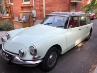
My new challenge - 1964 ID19F Safari

Over 20 years of focused, determined, scientific, genius and mostly rational work.
You can't suggest that the modern computerised ones are any better.
We are looking at a 65 year old design, and a 57 year old example that had failed for the first time.
Your modern computerised version is sometimes giving trouble at 5 years old.
The computer still relies on signals from sensors which detect mechanical things,
And the engineering is not good enough.
For all your plastic pizzazz, zoom zoom advertising, blinking lights and giant touch screens, you don't get more reliability, nor more driving pleasure.
This re-creation of a masterpiece by Sven is going to bring more joy to the world over the next 50 years, then any new car built this year, guaranteed!

So....... please don't suggest it's "too much"....... it's actually "enough".
It may be the first time this system failed in 57 years but I am not sure it has worked 24/7 over that time.

Nevertheless, I admire the results and the design and the work that went into it, but I am sure if they had the digital technology available back then they would have preferred it. That said, a piece of wire in a pipe to control/regulate flow is simplicity genius but I think we can do better than that.

As for computers, they are just tools like the hammer in your toolbox. And just like with a hammer, it is all in the hand of the user. You can see people doing great things with a hammer and you can see people hurting themselves. Same goes for computers.

But my curiosity is more about how much of all that stuff would still need to be there if one moved to a computer controlled system. One thing is for sure, there would be massive weight and space savings, which has to be a plus in anyone's books. If you want to see what modern hydraulics tech is capable of, have a look on the utubes for Rotary SMP, a kiwi living in Austria who has just upgraded the hydraulics on an old Swiss CNC lathe. The result is a 75% weight saving and about as much space and the lathe is from the seventies, not the fifties. The modern modular (computer controlled) valve system used is just a work of art (not to mention the genius of the system design and the simplicity of service). As for reliability, I guess you can imagine given that the entire CNC manufacturing industry is using it. Citroen himself would probably be delighted to see it in his cars.
 
Last edited:
If you dive into any of the activa variants of the system then you can see what the system looks like when controlled by computer. The C6 would be the most complicated.

The beauty of the DS system is that every component is pretty simple and endlessly repairable. A slide valve connected to a rod to control the car’s eight is not prone intermittent electrical faults.
 
Some would argue that anything with more than a single sphere for each wheel and an accumulator is enough .. then consider the 4X4 Peugeot 405 that relied on only ONE sphere for the rear suspension. I run a Hydractive 3+ and consider the so called advantages something of an exaggeration.
I have always maintained that the DS front suspension was flawed in that the exhaust side sphere has a harsh heated working environment, which also limited the engine space's width and the exhaust space ( First nose Ds got the exhaust heat well away from the engine space )..... far better to have it SM style where the spheres are away from the engine heat and can at least get some cooling air... even better to have the LOWER arm as the loaded one connected to the sphere where it could be placed in the wheel arch's cooling air flow.
 
In normal operation, one sphere per corner is ideal, but some installations were too soft for many. The benefit of Hydractive (but not Hydractive 3, which is really non-Hydractive) and Activa systems is more toeards the limits. An early C5 HDi with Hydractive 3 and 15" rims is likely a more consistently soft ride compared to some of the later C5s with Hydractive 3+ and larger rims. C6 is an entirely different animal to all the others because it has no dampers in the spheres and relies on the switching between damping laws in real time. At low speed it feels much more like an older D than most other models, to the point that some people have commented that it seems to need new shocks! Progressive Hydraulic Cushions in C5 Aircross and the later Cactus (not sold in AU) is an entirely mechanical system that is basically soft in the middle and stiffens up a lot towards the ends of the travel - rising rate. The new C5X has a further development that does incorporate some electronic control.
 
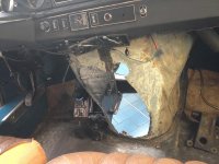
This is one sort of modification that the DS could have benefited from when in production. Access to the timing chain end of the engine and an escape route for the heat ??? and using floor space that would not be missed.
This is from a Facebook group showing mods including a Borg Warner overhaul, a 5 speed BVH conversion and lots more. It also shows small mods to rear suspension mounts that may not have been necessary.
https://www.facebook.com/photo/?fbid=181116777347101&set=a.180036790788433
 
Firstly iI don't think the timing chain access is a real issue. If the cam is not overloaded with accessories, chain life is adequate.

The centre hump in these pics does not give access to the timing chain, it does not improve airflow. The floor below the added centre console has not be removed, nor opened to the muffler chamber. It will help to stiffen the structure, however with that roll protection frame, I don't think that stiffness is an issue.

The rear suspension stiffeners might reduce the potential of fatigue cracking of the mount.

Sorry to add to the deviation of your thread, Sven.
 
I believe that is the chassis for Harry’s rally car. The list of modifications is quite extensive
 
All right, back to the main game: question: I could only find the carbie setup procedure for the post 72 Weber. Mine doesn’t have the air adjustment screw (1) in the photo, just the two butterfly screws and the idle mixture off to the side.

is the adjustment of my 24/32 DDC A1 the same?

- 1.25 turns for primary
- 1.5 for secondary
- 1.5 out for idle mixture

here the later setup…

B6A64ABE-94AF-4EEF-AE50-D662856FB8F9.jpeg
 
Hi Sven, I reckon that would be a good place to start.
That procedure looks good, however without the air screw you will adjust the idle by the butterfly stops. But which one?

I would:
Having adjusted the mixture screw to max rpm, then set the idle speed.

If the idle rpm is too high, adjust the secondary butterfly stop out up to 1/2 turn max. If its still too high, then use the primary stop screw.

If the idle rpm is too low, set the primary in by 1/2 turn max. If its still too low, set the secondary in by 1/2 turn max. If its still too low, then use the primary stop screw again.

Check the mixture again to max rpm, then
always finish adjusting on the primary stop screw.
 
I'll just leave this here......
 

Attachments

  • IMG_1723.jpg
    IMG_1723.jpg
    238.5 KB · Views: 145
Finally some success - I have been prowling up and down the house a bit as I had a “lull” in things to do on the Safari.

The seal kit for the power steering is on the way, as are two more new brake callipers pistons. Those arrived Saturday, so in they went and I am hopeful that me sanding the calliper groove will have eliminated any leaks… time will tell.

so I installed the callipers again, put a blanking plate onto the steering feed pipe and connected the radiator again.

started the car and set up the suspension levels. The rear HC rod needed a little tweak to lower it, the front needed to be a bit higher. After a decent amount of rooting around I got the levels right. Acutely aware that I didn’t want to get squashed when adjusting the front sway bar level.

Then onto the brakes and like last time - no feed to the pedal - bugger me! It is doing my head in…. After the usual checking of lines and leaking LHM over the floor I still didn’t find a reason why the brake circuit isn’t working…

Not sure what made me take the mushroom off, but I did and in frustration pushed the pedal without the mushroom…. Whoosh! Pressure and oil flow galore - geez… Idiot me! I installed the plate that holds the rubber with the nut in reverse! It needs to be as per photo below…

That’s all it was! Sometimes it’s the simplest thing! 😄👏

D2AF0F5C-24E6-4FBB-A487-496EF96DA762.jpeg


now all I need is the steering rack back in place and I should be able to ‘drive’. Outer panels should be back in the next two weeks as well.
 
At the risk of further derailing Sven's excellent account of his amazing work ... Oh to have his skill, talent, dedication and devotion.
To have had the design incorporate a rear ward tunnel ( as depicted in the shortened DS coupe above ) would have allowed more room for the exhaust to have exited rearward, allowed more room for a harmonic balancer ( which was fitted to some long stroke and short stroke engines ) and allow timing cover access. Something that is seriously neglected on the transverse engines in recent designs. Timing belt access in C5 X7s for example if horrific.
It may have allowed the actual footwell on RHD cars to be more generous. RHD clutch pedal access over the throttle pedal rod lump is pretty awkward and minimal. The DS design is biased to LHD floorspace which is more generous and flat ......... I suspect a rear tunnel would allow heat to escape rearward and therefore improve the marginal working environment for the rear RH engine mount and exhaust side front sphere. First nose Ds were different in firewall shape from the later "noses", so some variation was possible from Paris. A bolted in panel was part of the firewall design of 4 cylinder tractions and supported the rear centreline engine mount, so a factory engineered false panel would be entirely feasible.
 
Top