Berlingo M59 Wiring Diagram for Fan cooling

softweigh

Member
Tadpole
Joined
Oct 29, 2020
Messages
47
Location
Perth WA
Hi Guys

Still struggling with the fan on my van ..I only have a big single fan in front of the radiator and it only runs a high speed and the only wiring diagram I have shows 2 fans ..I have been told that it uses a big resistor to run slow fan and hi-speed fan and I really need to get it working correctly.

Anyone got a wiring diagram???? Any help would be appreciated

Chris
 
Hi Chris,
No disrespect intended but why do you "really need to get it working correctly"?
In your other posts you said the override switch that you installed "works well".
Is this to do with the engine temp going up at high speed?
Or is the work-around just unsatisfactory?
 
Ok Firstly Kenny - VIN: VF7GCKFWC94386825 Much appreciated ...

ozVTR ...As far as I'm aware the fan runs at two speeds so it seems most of the time I can have the fan on low speed and only might need it on high speed in heavy traffic .. if I run with no fan the temp eventually creeps up to where I feel it needs the fan to kick in or run all the time (when I bought the car the fan ran all the time and had been permanently bypassed. It's hard to also see what the the temperature is as both fuel and temp gauges are over reading heaps!!! With the temp gauge indicating between 90 and 100 an IR thermometer reading on the top radiator hose reads 60 and the lower 49 so it's way out ..My fuel low light comes on when the fuel gauge gets between 1/4 and half so also way overreading .
 
Here we go
 

Attachments

  • BERLINGO VU (M59) - D4EA54P0 - Operating principle _ Cooling system.pdf
    236.8 KB · Views: 740
  • cooling.pdf
    237.2 KB · Views: 851
Hmm maxifuse #1 seems to be the first port of call. Labeled MF1 on the diagram.
Check for 12V between pin 1 of the 8-way black connector receptical in the BSM and chassis ground.
And/or remove both relays on the fan shroud and check pin 3 of the wiring loom connectors for 12V.
They are all connected to the battery positive so 12V should be there all the time.
Where did you run your over ride switch to/from?
 
P.S. in the LEXIA scantool, linear parameters from sensors can be adjusted by a matrix called "laws". So you can tell the relevant ECU what the top, bottom and points in between should be for a particular sensor. However I don't understand why your fuel gauge or temp sensors "laws" would be wrong.
 
Awesome ..will do that .. a previous owner ran a cable from 12V in the BSI box it looks like direct to the one relay in the black box next to the radiator .. it ran the fan at full speed the moment ignition was on. I just cut the cable and ran a new cable back into the cabin with a toggle switch so I could kill or switch in the relay when needed.
 
I'm puzzled cos they appear to be linear but simply over-read .. the temp gauge when the van is cold (overnight) starts at 70 degrees when the ignition is on and then rises steadily (with no fan) and settles between the 90 and 100 mark (temp at this stage with an IR thermometer on the rad hoses is 60 top and 49 bottom yet the gauge says it's 95 ... the IR reading on the actual sensor base (I replaced it) is only around 70. The Fuel gauge goes way over "F" when the tank is full yet kicks the low fuel light in between 1/2 and 1/4!! It's almost as if the instrument panel is getting more than 12 volts cos the reading also rises slightly if the RPM goes up. In older vehicles I remember that instrument panels often had a voltage regulator supplying then say 10 volts so their readings wouldn't be affected when the battery gets a feed from the alternator and can be anything from 12v or lower up to 13.6v Thanks again for all your help!!
 
Most petrol engines operate at a coolant outlet temperature of between 85 and 90 degrees Celsius (very approximately!!).
If you have a look at the temperature value table (3.1) in the first PDF, you will see the cooling fans wont come on until the outlet temperature reaches 97 degrees.
Most temperature indicators only start at about 50 degrees because below that the engine is very inefficient and has poor performance.
The real problem is that you don't know the full history of this van and what has and hasn't been done to it.
 
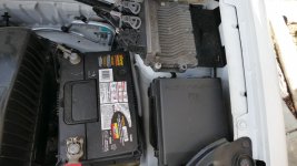
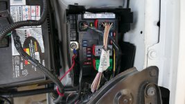
Very true .. I can find MF1 on the schematic but I'm struggling to find it on the van .. I assume that it's in the plastic black box on the right of the battery and just below the ECU?? All the fuses in there are just marked by max current ... there is a loose loom inside this box with a relay wrapped in tape and also a "main fuse" in the loom in a little plastic box that all looks OK! I have attached photos to see if I'm looking in the correct place!!
 

Attachments

  • box001.jpg
    box001.jpg
    329.1 KB · Views: 377
  • box002.jpg
    box002.jpg
    354.6 KB · Views: 548
Definately a thin cable so light current so it must go to one side of the relay coil as when I flip my dash switch I added the relay energises (you can hear the relay click in) and switches the fan in but a full speed only.
 
That's not good news.
If the fan is running from the relay then neither the relays or the maxifuse are your problem.
Can you tell me which pin on the relay the wire is connected to? It will be pin 1 or pin2?
By the way the maxifuses are underneath the BSM (the fusebox in your second picture). You have to take the BSM out to get to them.
 
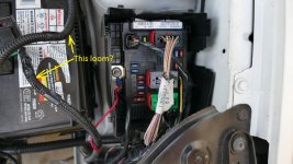
there is a loose loom inside this box with a relay wrapped in tape and also a "main fuse" in the loom in a little plastic box that all looks OK!
That doesn't sound right. Do you have any after market accessories like spot lights, audio amp or something like that?
 
Are you talking about this loom? It's not OEM.
 

Attachments

  • index.jpg
    index.jpg
    287.7 KB · Views: 1,010
The maxi fuses MF1 is under the psf.
It is the big fuses.
You need to lift the fuse box and you will see them
 

Attachments

  • fuses.pdf
    260.8 KB · Views: 338
Does this loom and relay have anything to do with the radiator fan business?
If so, a previous owner ran a wire from the BSI (fuse box in the glove box) to the BSM (in the engine bay) then to the fan relay via this loom?
None of this makes any sense. The radiator fan speed relays need power and ground to operate.
'Normally' the power comes from two different sources in the BSM, F8 and F4. The grounds are supplied from the engine ECU on two separate wires labeled 1540 and 1550.
If this magic wire (from the BSI) is providing +12V where is the ground? The engine ECU wont provide a ground until the temp sender reaches 97 degrees.
Is there an extra wire going to ground from the working radiator fan relay?
If the switch is grounding out the relay, why run all those wires? One relay power comes from the ignition switch and the other is switched via a relay in the BSM! So when you turn the ignition off, power to one relay is cut instantly and power to the other relay will be cut by the BSM. So just run a wire from pin 2 of each of the fan relays through a switch to ground! Simples.
So to have gone through all of the rigamarole that the previous owner did, BOTH the engine ECU control lines failed AND the two sources of power failed.......I don't think so.
My best guess is that the engine ECU is not providing a ground to either of the relays...but that's just a guess.
As Jonny5 says "need more input".
 
Last edited:
I would try bring car back to standard and run some tests.
Disconnect extra wires and tape up.

Then check all fuses if ok and power at fuses.

Then check relays and fans.

It is fairly old school system so not to complicated.
 

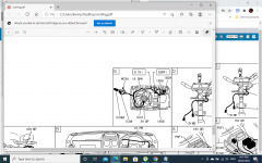
Attachments

  • fans.png
    fans.png
    203.9 KB · Views: 1,884
Top