'87 505 GLS Fuel Injection System

The pre-filter draws from below as you suspected. It draws through vanes and can catch a fair amount of fine dust. Doesn't catch much these days since I don't do much dirt road driving anymore.

I think I'd trust a GPS phone for a speed check, even ahead of Jaeger's best effort.

Don't worry about how we RHD people suffer. The 404 was easy to work on. I guess, like the 504, extractors were a bit messy getting around the steering column. We deserve more sympathy because Peugeot never bothered moving the wipers so the driver might get a good look at what he was about to hit. As for the 604, I suspect LHD and RHD suffer equally. At least with all my Pugs I can be grateful I don't have a gearbox and diff shoehorned in there too.

I think you have the insulation of the IAT sensor a bit backwards. The IAT is typically a screw-in brass fitting that will necessarily absorb heat from whatever it screws into. The important thing is that the thermistor and its associated wiring be insulated from its own brass fitting so the thermistor stays at the temperature of the passing air stream, not the metal it's mounted on.

But Jo's comment has got me thinking of going closer to the head too. While on the IAT subject, one thing that is really critical with the Megasquirt setup is injector "dead time". If it's wrong, the temperature compensations can mess things up more than they help. Dead time varies with voltage too -- I recently replaced my alternator and the jump from 13.5V to 14V has seen everything get noticeably richer. All of this is configurable on the MS; getting it all configured correctly is a challenge. Not there yet and I'm toying with a few experiments to accurately gauge my 505's dead time against voltage.

Plenty more hours of torment for you yet.

Have fun,

Rob.
 
Hi Rob,
As promised, here are a few pictures of my 505's engine bay.
air_intake_side.jpgengine_bay.jpg
As you can see, I actually already have a really good air intake system, I'm kind of an idiot for trying to screw with it! The intake is going to be pressurized at higher speeds. I think I should just swap out the AFM and call it good.
One thing I was curious about, why did you tee off of the heater controls for your MAP sensor? Was there a reason you couldn't just use the vacuum advance hose? Is that a ported vacuum source or full? It looks like it may be in front of the throttle plate, so I'm guessing that is why you didn't use it (that would make it ported if I understand correctly) Ported should have no vacuum at idle, so I guess I can just test it.
Also, do you notice any difference in how the car runs when you change heater positions? That's probably unlikely, as the vacuum reservoir is supposed to provide a cushion there, but what if it fails/leaks?

Edit: I realized that last bit was a little silly of me, the entire system is connected, so it would be highly improbable that the heater controls would make much, if any, difference. It really doesn't matter where you tap in to the manifold vacuum. Vacuum will automatically equilibrate the pressure almost instantaneously!
 
Last edited:
Hi Wade,

That intake setup looks pretty good. I think you're right to leave it alone apart from chucking the AFM (which is a bit of a restriction).

You answered your own question on where I hooked the MAP sensor. MAP's pretty forgiving. In the early MS days they wondered how responsive the MAP sensor would be and tried with (IIRC) 100 feet of vacuum hose and found it indistinguishable from having a short hose. The heater controls have no noticeable effect. I guess if the reservoir springs a leak it might confuse the MAP sensor a bit, but if the leak was that bad it'd also bump my idle speed and I'd likely hear the hiss in the cabin too. I can think of worse failures.

The vacuum advance port isn't what you want -- it's ported vacuum as you say. Mine's blanked off.

Have fun,

Rob.
 
If I may share some info from my time back when working at dealers of Ren and Pug brand new. I became a lover of the R25 Renault after a few short drives but it wasn't until I got the chance to drive one 200 kms I could really appreciate the Renault tuning. A 3 speed electronic Renault box too. At 100 kph nice and smooth in top I went out to overtake a line of traffic, it kicked into 2nd and took us to 150 kph or so and into top and just kept going, all smooth and business like. Not a rocket but plenty quick! The 505 had no hope compared to the Renault set up. Almost embarrassing in comparison. I was a true Peugeot 504 Ti man before that day, it changed the way I looked at things Renault! I still have a Renault as my work car.
The 505 STi ZDJ/K bosch K was much nicer engine than the L jetronic. The same head, cams ign curve. It ran 2 deg advance on the cam sprocket and a touch more compression at 9.7 :1. However it was never a match for a Fuego which is a 2l engine and ecu ignition and all were blown away for torque and speed by the R25 automatic leaded version. The cams are all the same. Sometimes the timing was changed by the factory sprocket. The engine management combined with the R25 head and inlet was the key. The ports in the R25 head are a touch smaller and taller with longer runners. If you check the sprocket it has two timing marks. The single lump as opposed to a twin bump is factory STi straight up cam timing. Advancing this another 1/2 keyway gives you a cam 4 deg advanced to the crank. More dynamic compression and more tore. Both fuel and ignition need to changed to get power and revs from the combo. The best way is learn from the R25 and Fuego. They had a toothed flywheel. You can use a trigger wheel from Triggerwheels in the UK or make something in a distributor body. I have used the Nissan 360 CAS onto the Pug dist base. Accuspark items are another choice I like. The key to power is dead accurate ignition and that's what the R25 had with the positive crank sensing. The Fuego had the same set up and ran a small carb and boy they were very fast little cars back then. The killer in these engines is blowby oil venting back into the inlet. You have to stop that from happening by cleaning the baffled valve cover venting and setting up a vent can or such. High revs in the 505 engine will push oil into the inlet and we get pinging every time! You can get the engine to run Stoic. at idle and on cruise provided you can set the ignition points with accuracy. My thoughts for your project are to get the engine breather right first, check your cam timing and I must let you into a trade secret, set the valve clearances to 0.15mm cold on both inlet and exhaust. Some engines ran an air injection system which was a very clever set up but the reed valves could leak and blow exhaust into the air cleaner. That would be worth checking too. I can give you the factory timing curves from the factory manual too so maybe we can get an MS2 and the ZDJ/L making music together. I have a friend who fitted one of these engines into his rally car in the 1980's. He kept the ignition and fitted 2 sidedraft webers. Much faster than his full on 2l pushrod rally engine, and that was a standard 2.2 out of his wrecking yard! Happy to help with info if you want it, I hope the above is helpful to you and others. I'm off to read more MS2.
 
Stew,

A helpful suggestion from a keen follower of your informative posts.

A long post like the above is very hard to read and inwardly digest without a few page breaks.

So others can get maximum benefit from you freely given "secrets". I've taken the liberty of reformatting your and re-posting the text below.:)


If I may share some info from my time back when working at dealers of Ren and Pug brand new. I became a lover of the R25 Renault after a few short drives but it wasn't until I got the chance to drive one 200 kms I could really appreciate the Renault tuning.

A 3 speed electronic Renault box too. At 100 kph nice and smooth in top I went out to overtake a line of traffic, it kicked into 2nd and took us to 150 kph or so and into top and just kept going, all smooth and business like. Not a rocket but plenty quick! The 505 had no hope compared to the Renault set up. Almost embarrassing in comparison.

I was a true Peugeot 504 Ti man before that day, it changed the way I looked at things Renault! I still have a Renault as my work car.
The 505 STi ZDJ/K bosch K was much nicer engine than the L jetronic. The same head, cams ign curve. It ran 2 deg advance on the cam sprocket and a touch more compression at 9.7 :1.

However it was never a match for a Fuego which is a 2l engine and ecu ignition and all were blown away for torque and speed by the R25 automatic leaded version. The cams are all the same. Sometimes the timing was changed by the factory sprocket. The engine management combined with the R25 head and inlet was the key. The ports in the R25 head are a touch smaller and taller with longer runners.

If you check the sprocket it has two timing marks. The single lump as opposed to a twin bump is factory STi straight up cam timing. Advancing this another 1/2 keyway gives you a cam 4 deg advanced to the crank. More dynamic compression and more tore. Both fuel and ignition need to changed to get power and revs from the combo. The best way is learn from the R25 and Fuego. They had a toothed flywheel. You can use a trigger wheel from Triggerwheels in the UK or make something in a distributor body. I have used the Nissan 360 CAS onto the Pug dist base. Accuspark items are another choice I like. The key to power is dead accurate ignition and that's what the R25 had with the positive crank sensing.

The Fuego had the same set up and ran a small carb and boy they were very fast little cars back then. The killer in these engines is blowby oil venting back into the inlet. You have to stop that from happening by cleaning the baffled valve cover venting and setting up a vent can or such. High revs in the 505 engine will push oil into the inlet and we get pinging every time! You can get the engine to run Stoic. at idle and on cruise provided you can set the ignition points with accuracy.

My thoughts for your project are to get the engine breather right first, check your cam timing and I must let you into a trade secret, set the valve clearances to 0.15mm cold on both inlet and exhaust. Some engines ran an air injection system which was a very clever set up but the reed valves could leak and blow exhaust into the air cleaner. That would be worth checking too. I can give you the factory timing curves from the factory manual too so maybe we can get an MS2 and the ZDJ/L making music together.

I have a friend who fitted one of these engines into his rally car in the 1980's. He kept the ignition and fitted 2 sidedraft webers. Much faster than his full on 2l pushrod rally engine, and that was a standard 2.2 out of his wrecking yard! Happy to help with info if you want it, I hope the above is helpful to you and others. I'm off to read more MS2.
 
Thanks Teach! :D I can rave on a bit. Will I still get a gold star or class free time for the story??

I'm just going over all the ideas I've had regarding accurate crank position sensing on the ZDJ as this is the secret to reliable power and running.
VR sensor is the safest bet yet in 505 there isn't a lot of spare room.
I use Nissan Cas adapted to the bosch dist cut down. It is very accurate but certainly not simple. I think maybe a tiny wheel in the dist housing might be the go or use the existing wheel in the dist as speed signal and a simple cam pos sensor for syncronisation?

Using the existing distributor as a trigger is not a good idea as the pickup coils fail as do the harnesses from it. Bit of fun to pass the time, Wade.

I guess I should ad I know nothing of what the US got but I suspect cam timing was retarded rather than a cam change, but without knowing the data on US engines I can't be sure. I do know that Australia emission rules follow Californian rules almost from early 1980's.

Lower static compression then retarding the cam timing reduces efficiency, thus dropping NOX which was a very big thing back then.
 
Last edited:
Very interesting Stew. I was triggering off the locked up dizzy more or less in its standard position and that was really crappy. Making it so its impulse comes at about 60 BTDC means that the crank speed is pretty accurate for when it needs to spark. Given that for the last decade or two I've been driving like a (spirited) granny, it's doing the job.

The Nissan CAS does look interesting though. The one Google gave me first had a 1 degree signal at distributor speed. That's the equivalent of a 180 tooth crank wheel. Mostly I have read about 60 tooth wheels in the MS forums, so it might be sending a bit too much info. Reading a bit further I see that Nissan have some other spacings so maybe it's just a matter of choosing the right Nissan dizzy.

Not meaning to hijack Wade's thread here, but a little more detail on squeezing the Nissan internals into the Bosch body would be good. Keeping the Bosch body and shaft, it would be a matter of getting the Nissan sensors well centred in the body and making some sort of adaptor to mount the wheel on the shaft. Right?

I'm normally with robmac on reading well structured paragraphs, but I honestly didn't notice until reading his posting. Interesting content counts for a lot.

Have fun,

Rob.
 
Gold star? better still six elephant stamps formatted centrally in the page breaks.

Thanks Stew, the information you post is valued and priceless to those of us wish to improve these engines.
 
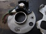
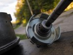
For interest sake, this is what the Ducilliar points styled dizzy looked like after I got to it.
This unit took care of cam and crank sensing in the same unit.

This is a head mounted dizzy, but could just as well be a block mounted one, the primary difference is the mounting arrangement.

Each
timing 3 - 1.jpgtiming 2 - 1.jpgtiming 1 - 1.jpg

Jo
 
The Nissan CAS is a beautiful piece of simplicity looking at it. Very clever and robust. However they are getting a little thin on the ground.
What I did with one for the ZDj was to machine down the Nissan housing and fit the pug offset key drive to the shaft. Same size shaft to Pug. I have them in my 2.2 and two XN 1 engines. It is hard to go past giving the ECU the exact degree and each piston position by using the Nissan unit ideally but I I have found a 36 tooth wheel with 1 missing tooth just as accurate with today's electronics. Bear in mind I was trying to run 18 psi into a ZDJ with 280 degree cam and 9.7:1 so ignition accuracy was paramount. Blew a few rings before I grew up and wore the big turbo out.
(New Paragraph Stew)
My understanding of engine management is that if the ecu can read each degree of crank and can also read where No1 tdc is the engine will be as good as it can be. So! If the software can calculate time between larger signals, as in 36 tooth etc we have an ideal option. An 18 tooth wheel off the cam and a No1 TDC signal might be worth thinking about.

Another way is one could use a tone wheel from an abs hub,take one magnet out and use the hall effect abs sensor . I'm going to work on that one! Here we are, I 've arrived at a suitable solution. The 307/308 HDi engines use what is close to the latest abs tone wheels, Now I'm cookin,. Shall be working on this one.
Too many ideas coming for a Sunday. I have to go and lie down now. thanks for your time friends.
 
Last edited:
Thanks for the information Stew! It is really encouraging to hear that ignition timing is paramount, because it is ultimately my goal to get it dead on!
My plan for timing was developed off of Megasquirt's advice pages. They recommend to attach a 36-1 missing tooth wheel to the crankshaft pulley. The primary vendor DIYAutoTune for some reason claims that a Hall Effect sensor works on their missing tooth wheels, although its relatively poorly documented on their website. I'll need to do some more research on that, as it was may understanding the VR sensors were the proper sensor for a missing tooth wheel.
Anways, Stew, with rock solid timing from the trigger wheel and wasted spark, I should be able to get dead-one timing accuracy right? Cleaning the oil breather system is a good tip, are you referring to the PCV blow-off that goes into the air cleaner? What exactly would a "vent can" consist of? Just an expansion tank for the PCV vapors to enter and relieve pressure?
I am waiting on a friend, Dave @ Eurocar here in Portland to give me some information about the differences between my ZDJL and your Australian ZDJL. Mine (the 851x), has an 8.8:1 CR and I've heard, but don't know, that the camshaft and head are slightly different. Your cam timing adjustment suggestion is interesting but I'm not quite sure if I follow exactly how that is achieved (the keyway lingo had be a bit confused).
It sounds like I need to do some more research to absorb the wealth of information you have provided. Much thanks!


To Robs,
I took another picture of my air intake system. It looks like the LU2 here in the states (since it was closed loop) had an IAT. It was sitting right in front of my face!
Fuel_injection_operating_principles.jpgIAT_pic.jpg
I pulled this info off of the IAT: Pierburg (W. Germany) 7-20271.00 12 V 7019
Maybe this part is still made/documented/has an equivalent that I could get the calibration info for.
I don't know how the idle adjustment works for you Aussies, but we have that knob near the IAT sensor we turn to adjust air for idle, so the IAT is measuring the air temp of the air entering the throttle basically. May be a good test for you Robs, OEM practice may be the best, we'll see!
 
Many thanks Stew. Good info (and nice paragraph break too!). The MS firmware around tach input is pretty complicated but it does do a pretty good job of interpolating crank position between wide pulses. I don't think it could keep up with a pulse every dizzy degree (without code modifications at least). Could perhaps deal with this electronically (frequency divider) but I'm sure an 18 tooth wheel at cam speed would do everything I'd want and be a big improvement on what I have now (effectively a 4 tooth wheel). For TDC sensing, leaving out two diametrically opposed teeth seems like it'd work (equvalent of a 36-1 at crank). Or leave out just one to support sequential injection and/or COP.

Please do keep us up to date with your thinking on using ABS sensors. It's an interesting thought.

Wade, even the open-loop LE2 had an IAT sensor. What I think you're looking at (the solenoid in your photo) isn't it. The IAT sensor is in the AFM, sitting in front of the sensor flap. Like you say, OEM practice is probably best -- that's why I put my first effort at an IAT in my AFM replacement tube. The solenoid (I'm pretty sure, but haven't checked) is to let in a bit more air to bump the idle when the aircon is running. Our idle adjustment is just the same as yours.

Have fun,

Rob.
 
Jo Proffi has used the 4 big tooth wheel in a dissy and a cam sensor I think, from his post.
 
Jo Proffi has used the 4 big tooth wheel in a dissy and a cam sensor I think, from his post.
I'm guessing it'd work more like an 8-tooth VR sensor though. With optical you get reliable timing of both the on and off events where a VR is only accurate on one or the other.

While we're thinking laterally, how would it go hooking a VR sensor up to the ring gear? Would still need a 1-tooth cam sensor of some sort (easily done by knocking tabs off the dizzy reluctor). The pulses would be coming too fast for the Megasquirt, but a fairly trivial bit of electronics could send every fourth or whatever (hmmm -- not so trivial if it's a prime number of teeth). On the surface, this seems a lot easier than all the work putting in special wheels, but maybe it'd just be an ugly hack.

Have fun,

Rob.
 
Rob,
I also figured out what the device that I thought was the IAT sensor. It is the idle air booster solenoid that is supposed to be triggered when the A/C is on! In case anyone else was curious.
Wade
 
Jo Proffi has used the 4 big tooth wheel in a dissy and a cam sensor I think, from his post.

They were all in the same housing.
The 4 toothed drum was in the middle of the housing and the single cast iron señor was in the 'lid'.

It didn't miss a beat, except for the day i forgot to do up the lid more than finger tight and it fell when the car hit a pothole. Doh.:crazy:

One of the things I liked about the dizzy setup, it was dead easy to install and set up. another thing was it was all really high up in the engine bay on the head….My aim was to make the engine weatherproof and I succeeded in that.
Could flood the engine bay with a hose and it wouldn't miss a beat.
Cant say the same for my modern renault with its top mounted hydroscophic water-well spark plug tubes that have a magnetic effect on rain water. :mad:

Jo
 
On the topic of crank triggerring, who can tell me how this TDC sensor works? I found this in the ZDJL shop manual. I don't know what type of sensor this is, I'd guess a VR as it seems to sense a 'hole' in the flywheel at TDC, and I haven't seen any mention of it with regard to the Fuel Injection system.
TDC_sensor.jpg
What the hell is this? Can we make it work for us? A toothed wheel sensor on the flywheel with a TDC trigger perhaps (if the computer can keep up).
I'm curious as to where this goes, perhaps the tachymetric relay?
 
Last edited:
It's nothing exciting I'm afraid. Just goes to the diagnostic plug and triggers a pulse at (I think) TDC for 1 and 4. I don't think a one toothed crank wheel gets us very far.

I've never set eyes on Peugeot's diagnostic plugger-inner, but I'd guess that, combining the TDC sensor with a cylinder 1 spark pickup, you could work out advance, not just at idle, but throughout the range.

Have fun,

Rob.
 
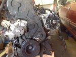
zdjl_pulled.jpg
Alright Rob, I scrounged on the North American Peugeot Facebook page and found a picture of the ZDJL engine mid-pull. Gives us a pretty good view of what we are working with here. It's kind of hard to see, but there is a recessed rim with a flat surface that is indented just before the pulley's frontmost flat surface. I think it would be difficult to drill and tap the frontmost flat surface on the pulley without compromising the A/C belt, but that flat recessed rim may be promising (I felt it out with my fingers yesterday).
In theory, one could punch and drill four (or however many you choose) holes along this rim. A little tapping and a few fasteners may very well hold everything in just fine. Most trigger wheels are thick enough that being fastened so close to a flat spot on the pulley would likely have no deforming effect.
That brings us to our classic demon, mounting the sensor. This picture does a little less good here.. The mounting will certainly take some creative measures. It looks like there is a stud coming from the damper, and what appears to be the power steering mount stud(?).
Aha! Perhaps a friendly water pump stud could be persuaded to come forth a bit and bolt down a bracket! This may require getting longer studs, but that's no issue. Of course this all is very speculative given the engine is already partly disassembled. Just throwing some ideas out there.
 
Last edited:
Hi Wade,

I agree on the pulley. I later realised that my (PM) suggestion yesterday of a centrally mounted flange would just introduce potential problems -- and the pulley itself is pretty much a centrally mounted flange. Definitely mount on the central part -- I don't know how likely it is for the outer to slip, but might as well keep that out of the equation. You're kind of spoiled for choice for bolts to mount the sensor from. It's also a possibility to weld something reasonably sturdy to the A/C or PS brackets.

One obvious but easy to miss thing to keep in mind, especially with that photograph, is where the belts run.

You've goaded me into action. I think I'll go ahead and do a proof of concept using the flywheel ring gear. I'll warm up to it first by asking a "How insane is this?" question at the MS2 forum.

Have fun,

Rob.
 
Top