206 GTi cutting out off idle

Stuey

Well-known member
1000+ Posts
Fellow Frogger
Joined
Jul 31, 2001
Messages
6,690
Location
Perth, Western Australia
Hi guys,

A weird thing happened this afternoon. The 206 has been running pretty much perfectly since I got it.

I parked at the station today, and on the way home it firstly didn't indicate left (no flashing) then was fine, but then started cutting out off idle as soon as I moved the throttle. I revved it and got home but each time I came to a slow it would almost cut out. Now a couple of hours later, it starts fine but wont take throttle at all without stalling.

I'm being a bit slack here and hoping this is indicative of something, because my son's in hospital with a strange disease they're trying to diagnose and I haven't time to check anything yet as we've been a bit preoccupied. I haven't had time to check all connectors on the loom although I did have a cursory look and fiddle.

There are no engine/ecu lights illuminated on the dash. I did find the battery negative was loose and tightened it. I also played with the battery cover yesterday while I was topping up the brake fluid (just saying because I may have bumped the lead - could this cause an issue?). However it ran fine yesterday and this morning.

Any ideas?

Cheers

Stuey
 
Hmmm, I wasn't aware that a code can be stored without a dash lamp being illuminated - is this correct? Just searching around the Google Emporium it appears so. I might try my crappy OBD unit.

I'm guessing it may be the TPS causing issues but I'm going to study how the Magneti Marelli 48P setup works. I usually get to know this for each of my cars to aid in times like this but haven't in the case of the 206....yet. I've reseated the plugs on the loom around the throttle, and the MAP sensor, but it made no difference. I think the purchase of that Delphi code reader might be brought forward!

It certainly seems like fuelling isn't following air volume, so it leans as soon as you open the throttle (cable in this car) and stalls.

Unfortunately I have to work so it's only a night time operation...at least son is out of Charlie Gairdners.
 
Yes the display of an engine light is part of the strategy of the engine ecu so there is a list of things that a fault code will do I might have a list somewhere for a 4.8


Garage C5 X7 3008 XTE
Gone but not forgotten 206 GTI 180 306 XR SED 405 MI16 x2 xzara VTS 406 SV 206 XT Berlingo 2011 (best car ever) 306 HDI 307 XSE HDI touring
Fix it right the first time
 
Last edited:
Thanks David. Are you saying it should show a light whenever there's an engine fault code stored?

I've removed the TPS and there is a fixed resistance between all three pins, each different but constant no matter where the thing is turned. I assume this is not right. Between one pair of pins is circa 748 ohms, the other around 51 and the other, about 2. The display on the DMM doesn't even flicker. If this is the failure mode, it's pretty weird! I wouldn't expect it to go from a gradual resistance variation to this!! Assuming it is meant to be gradual, which I believe it is.

I may pull the metal cover off and have a squiz.

The MAP sensor is clean, but other than that I haven't done anything else as surely its the above!
 
...fifteen minutes later...

I popped the cover off the TPS and now it makes more sense. It's not just a simple potentiometer, but also has a small printed circuit with two tiny SMD parts potted in a very tacky water clear jelly. So it's quite feasible a resistor or something has gone west making the results above more logical. I think.

And for reference the OE part no is 9642473280 (also 1628.JX or 1635.Z9).
 
Last edited:
No sorry meant yes it can have plenty of codes that don’t set a light I couldn’t find anything quick be normally it looks like this
Code PXXX
Say it’s a fuel level sensor open circuit
First you get code setting criteria
Open circuit in fuel level circuit for two driving cycles.
Then you will get a list of things that it will do when fault occurs-
Lighting of warning lamp No
Downgraded mode No
And finally disappearance criteria
Can be 3 driving cycles etc etc
If that makes sense


Garage C5 X7 3008 XTE
Gone but not forgotten 206 GTI 180 306 XR SED 405 MI16 x2 xzara VTS 406 SV 206 XT Berlingo 2011 (best car ever) 306 HDI 307 XSE HDI touring
Fix it right the first time
 
Anyway some 206s have over charging alternators and can cause weird things and checking in the airbag or abs can log a over voltage fault Mitsubishi branded alternators are very common for this but vacuum leak sounds on the cards as well.
That Delphi will be a good idea the code 206 keys


Garage C5 X7 3008 XTE
Gone but not forgotten 206 GTI 180 306 XR SED 405 MI16 x2 xzara VTS 406 SV 206 XT Berlingo 2011 (best car ever) 306 HDI 307 XSE HDI touring
Fix it right the first time
 
Cheers.

I may have spoken too soon. Fiddling with the TPS thinking it's shot, I found it has a programmable hall effect sensor IC in it (marked '215DB') which gives an analogue output. So there's no contact, just magnets and the IC that's set for a linear output in response to differing magnetic field strength...and I feel what this probably means is that it wouldn't produce a linear change in resistance, but rather, only a change in voltage output while connected to the 5v source. While it could have been stuffed, I don't think I'd proved it with the DMM - but it's definitely broken now! Arrgh, what a prat....a bull in a china shop.
 
Last edited:
The plot thickens...I'm not spending a lot of time on this, but I had another look today.

I carefully reassembled the TPS until I can get another one (quite a process actually as the bond wires were welded on the original and were a bugger to now solder), reinstalled it and it tests fine. The ECU is providing 4.99 volts and the TPS output is between 0.7 and 3.96 which I believe is pretty close to correct, looking at the Magneti Marelli data for the unit. The gradient seems to be smooth (I don't have an oscilloscope yet...). However, I'll buy a new TPS because I reckon this one might not be reliable now!

I've checked the cam and crank sensor connectors and removed the sensors to clean and check for damage. I've checked over all vacuum pipes. I've checked the coolant temp sensor's resistance at about 25C and it's about what would be expected (so not open or shorted).

I removed the idle valve solenoid/stepper motor and cleaned it up. Its piston can be observed through the secondary intake making small adjustments and maintaining idle while the engine's running. It reacts quickly to small changes to the throttle position.

There are no codes stored. The throttle body and butterfly are shiny clean.

What I have found it that it is only just coming off idle that the car stalls. If I carefully feather the throttle butterfly through the first 3-4mm of travel at the edge of the butterfly, the car will rev fine and you can maintain any revs desired. Close the throttle and it idles fine, and smoothly at the correct idle revs. JUST crack the throttle and it goes to stall. Hold it just cracked open and it stalls. It will idle for as long as you want smoothly and without issue as long as you don't crack that throttle a touch.

So what happens at the transition from idle control to throttle control? I shall persevere...
 
Last edited:
My first port of call would be to plug in a Lexia and do a global test. I'm in Brisbane but there's probably somebody in Perth who could help out. If you want to buy a Lexia the good ones (which work on the 307 and later cars) are about $90 off eBay but take a few weeks to arrive and a few lifetimes to get the software running. While a Lexia only works on Peugeot/Citroen cars, it's super useful in that not only can you read faults, but you can also test actuators. So you could click a button and watch the throttle open (it's fly by wire on 2003 models right?). Same for the idle air control valve. You could also use a household vacuum on the throttle body to test the map sensor (it doesn't respond to positive pressure).

206 keys don't need to be coded if that's what you were saying. There's a procedure of holding down the button, starting the engine etc that trains the computer for the new key. No OBD tools required. At least on my '99 GTi that was the case.

My guess is the MAP sensor is ignored at idle since the engine RPMs are known and the IAC position is known, and everything is calibrated to the stock intake. The TPS must be working to some degree for the ECU to even know that it should be in idle mode.
 
206 keys don’t need to be coded ???? They all run a transponder chip pre and post mux I think the only way yours could have don’t that is someone put a chip in the code reader so you have no immobiliser.
With regards to pp2000 lexia don’t bother with the clones they are a pain do a ds150e there is nothing really to configure on a 206 anyway


Garage C5 X7 3008 XTE
Gone but not forgotten 206 GTI 180 306 XR SED 405 MI16 x2 xzara VTS 406 SV 206 XT Berlingo 2011 (best car ever) 306 HDI 307 XSE HDI touring
Fix it right the first time
 
No, it's a cable throttle.

I didn't mention anything about the keys; I'm not sure what you meant.

Unfortunately I'm a bit busy so this one is going to take a while to sort out.

David, can you remember where the vacuum pipe is for the evaporative canister purge setup on the intake on these? I can't see it anywhere on the intake manifold and was just interested, as I didn't see one while I was checking the vacuum pipes.
 
The plot thickens...I'm not spending a lot of time on this, but I had another look today.

I carefully reassembled the TPS until I can get another one (quite a process actually as the bond wires were welded on the original and were a bugger to now solder), reinstalled it and it tests fine. The ECU is providing 4.99 volts and the TPS output is between 0.7 and 3.96 which I believe is pretty close to correct, looking at the Magneti Marelli data for the unit. The gradient seems to be smooth (I don't have an oscilloscope yet...). However, I'll buy a new TPS because I reckon this one might not be reliable now!

I've checked the cam and crank sensor connectors and removed the sensors to clean and check for damage. I've checked over all vacuum pipes. I've checked the coolant temp sensor's resistance at about 25C and it's about what would be expected (so not open or shorted).

I removed the idle valve solenoid/stepper motor and cleaned it up. Its piston can be observed through the secondary intake making small adjustments and maintaining idle while the engine's running. It reacts quickly to small changes to the throttle position.

There are no codes stored. The throttle body and butterfly are shiny clean.

What I have found it that it is only just coming off idle that the car stalls. If I carefully feather the throttle butterfly through the first 3-4mm of travel at the edge of the butterfly, the car will rev fine and you can maintain any revs desired. Close the throttle and it idles fine, and smoothly at the correct idle revs. JUST crack the throttle and it goes to stall. Hold it just cracked open and it stalls. It will idle for as long as you want smoothly and without issue as long as you don't crack that throttle a touch.

So what happens at the transition from idle control to throttle control? I shall persevere...

Interesting pursuits.

I would try to see if I sprayed some start ya bastard or something in the intake if it keeps running, just to decide if it is a fuel problem or an ignition problem (which I do understand are both electronic problems, but just for a rough indication). If you had an analog meter (or a VTVM) you could try to replicate the problem whilst measuring inputs on injectors and/or ignition. Oscilloscope would be even better. Or you could try a timing gun on one of the plugs if setup allows (coils not on plugs or use a plug wire extension from coil to plug).

My guess is your symptoms seem to point at a defective TPS. Is this cable driven or drive by wire? Either way, the rheostat/whatever sort of track it uses might have a worn out spot, difficult to see with a digital meter, you need a good analog, or a scope.
 
See my post about the TPS. It's a non contact hall effect unit which is fed a 5v reference by the ECU and outputs a linear gradually increasing voltage according to the position of a magnetic rotor driven by the throttle spindle, in proximity to the IC.

I'm getting a new one asap for the reasons above. Re-reading the data sheet I'm not sure about the results of my tests.

I keep meaning to grab a basic analogue voltmeter from Altronics.

I'll get there with this. Just need to be patient as I can only spend an hour here and there on it at present.
 
What voltage is it putting out? Somewhere in the range of 5+/- something? I am trying to figure out if you could bodge something say with an LED or something like that to check if it drops anywhere along the travel. A simple voltmeter gauge/dial with the correct range could be enough, no need for a multimeter.

I have a couple of scopes we could use to measure the culprit if you bring it down (you could borrow one, but if you're coming down it takes five minutes to measure the barstard).

Later edit.

Okay, I read the posts above. Your TPS could be outputting a linear ramp or a PWM signal (hence the components). Either way, not sure why they thought they needed to place those with the sender when they can very easily be on the main board in the ECU, but whatever, maybe they thought the signal was so weak it could be interfered with, who knows. Maybe if you knew what those little components were, or could post a picture, either way, a scope would sus it out easily. I would still suspect the sensor (hall/magnet) itself, the smd components are reliable enough to not be suspected off hand and the nature of the problem kinda supports the view. A defect in the smd components would manifest itself with less reliability at the one point where you keep detecting it. A resistor out of tolerance would shift the points where the correct voltage signal is put out, a semiconductor would crap the whole thing out (signal would be all over the place and so would be your throttle response).
 
Last edited:
Yeah, the voltage ranges from about 0.7 to about 4. Thanks for the offer I appreciate it but I need a new one anyway as explained in a post above. I accidentally dismantled it thinking it was a normal potentiometer type, then realised it had a chip inside. Duh. So I reassembled it, but that's obviously not ideal for reliability.

I'm pretty handy with electronics so could rig up something if needed. In fact I have some analogue voltmeters in the shed somewhere I think (old VU meters off an amp). But a cheap panel meter from Altronics would be handy anyway...
 
Last edited:
It's not a problem even if it has some electronics inside. We could try to suss out what they are and see what's what. I got it, you have a new one coming. Maybe when that one is in and the car works fine, you could donate the old one for a test? I am thinking about building a curve tracer, and that can identify dud semiconductors/passives of any kind in a jiffy with no destruction of the original circuit.

I am curious how it failed. The interwebs show a number of ways the hall effect ones can fail, would be nice if we could diagnose yours even if only for academic interest.

Hey, you could even buy one of my 'scopes one day (I am in the process of restoring my third, if successful one of the other ones is going to be surplus).
 
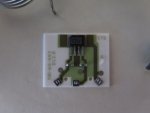
Here it is before reassembly:

IMG_0002.JPG

IMG_0001.JPG

The PCB is ceramic, and slips into that plastic device that looks made for it which then slips into a slot on the rotor. There were three sets of two thin bond wires from the board to the three contacts on the base. I had to make some up and resolder them, then reassemble with silicone. It was potted in a soft very sticky clear gel originally - a bugger to remove! If you search that IC marking it leads you to a datasheet for an MLX 90215 hall effect IC.

I'm not convinced the problem is with this unit despite my initial thoughts. I can't see the failure mode being a hole in the response. IMO it'd either work or not. If it was an old fashioned pot, then maybe.

PS...I thought a curve tracer was only for transistors (and valves).
 
Last edited:
By the way, I had the crank position sensor out on the weekend and it measured 49k ohms across the terminals according to my notes. It's a two pin inductive unit which my searches say should measure 400 ohms across the pins (which is across the coil). Some of these measure lower or higher, but not 49k.... I was so busy when doing it I hadn't looked into the specs and only found out about them last night but I'd returned the unit to the car. I'm annoyed as I'm wondering if my notes are accurate. I'll have to pull it out again.

I'm not even sure whether the crank sensor could have the effect I'm observing though especially when it's running at idle and higher speeds OK, although it is starting hard as well I've now found.
 
Top