1977 GS 1220 Pallas

​The next job on the car was to sort out the misfire I had. I checked the plugs, and found that the insulation was pretty average on one of the ignition leads, so I've got a new set of leads coming. At the same time, I wanted to do a compression test on the engine, so found my tester and hooked it up.

Results:
80, 85, 75, 30.

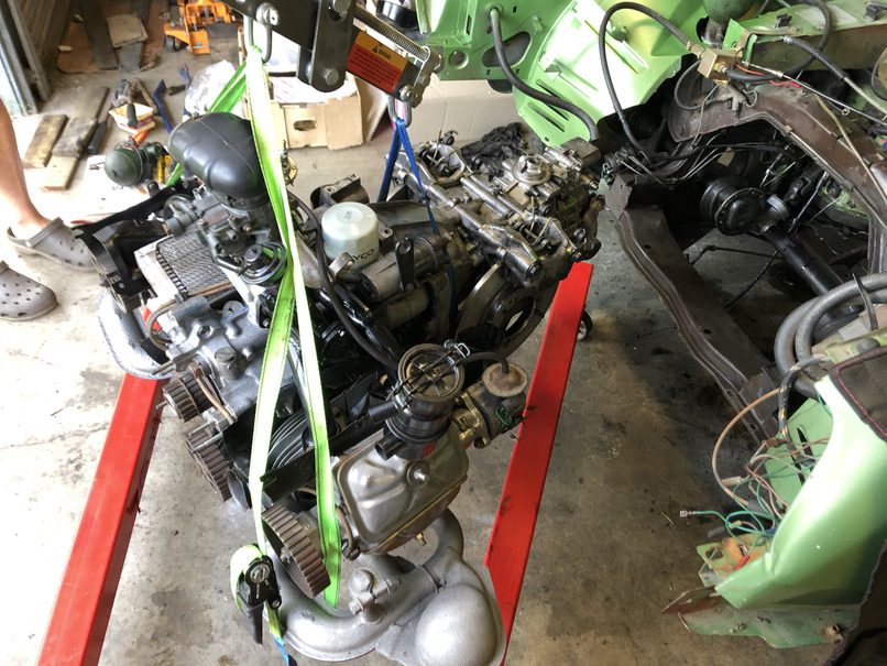
I pulled off the top rocker cover for that bank of cylinders, and verified that the valves were fully closing during the compression strokes, so its looking like busted rings, or a burnt valve.
Regardless, engine is coming out.

I've been planning to rebuild the engine, but I was hoping I'd be able to get rego sorted before that happened.
I've been gradually getting the required parts, and I have the lot now, so just need to make space in the old man's shed for it to happen, and schedule a day to get the engine/gearbox out.

1 step forward, and 2 steps back....
 
So, after the discovery of the bad compression, it was time to rebuild one of the engines.
Before that though, I saw a post from Greg of 50 Reno advertising a motor up at Gympie so Dad and I emptied out the Liberty, and headed up.

I ended up with the engine, and a few spare front hubs, steering arms, some guards and blower fans amongst other parts. Cheers Greg!

Gympie%20Haul.jpg


After we got all of this home, we got the got the engine into the shed, and started stripping it down.
Got the heads off, but on inspection, they were pretty worn out. There was a stuck valve, and I managed
to pull one of the spark plug threads out of the head :(

gympie%20engine%20-%20heads.jpg

Still, the bottom end turned over ok, so we ended up putting a plastic bag over the shortblock, and sticking it somewhere out of the way.

gympie%20engine%20-%20stripped.jpg
 
With the Gympie engine still needing a bunch of work, we made the decision to rebuild the original engine that came with the car, which had 2 pistons stuck in their bores.
I had a new set of pistons and bores, so as long as the bottom end was ok, we'd be fine. If it wasn't, well the gympie engine bottom end would work.

So, I started disassembling the original engine.
I removed the heads, and took them to Mike at Northside Cylinder Heads, for a recondition. He'd never seen anything like them before, but did a great job

Before:

Head%20-%20before%20recon.jpg


After:

heads%20-%20reconditioned.jpg


After heads were off, it was time to get the bores and pistons off. After a bunch of work, we freed the stuck pistons, and got the barrels, off.

The pistons were a pain in the arse. The gudgeon pins had corroded on the ends, and weren't coming easily. I didn't want to just wail on the end of the pins
through, as that would wreck the little end and big end bearings in the rods, which aren't easily replaceable.

I ordered a gudgeon pin tool, which promptly broke, so I ended up building a ghetto version out of iron pipe, which did the trick

Stock tool
gudgeon%20pin%20remover.jpg


Ghetto version
Ghetto%20Gudgeon%20pin%20remover.jpg


Pistons and bores out - you can see the corrosion on some of the gudgeon pins :(

old%20pistons%20and%20barrels.jpg


Now, I was left with a block with rods sticking out - next step was to remove the oil pump, and split the block

pistons%20removed%202.jpg
 
After removing the oil pump, and rotating the engine 90 degrees, I removed the right hand engine case exposing the crank
Crank%20%28Case%20Conflict%29.jpg


The crank is a pressed together unit; you can't remove the rods without pulling the crank apart. Luckily the big ends and small ends all felt pretty good

The engine runs three bearings, with the centre bearing acting as the thrust bearing. Both the front and rear bearings were in good condition,
but the centre bearing had a chip out of it, which meant I needed to find a replacement.


crank%20bearing%20chip.jpg


I managed to order a centre bearing from the UK, but it was a bit of a hedge, as part numbers had changed, and there were a variety of sizes used.
Factory spares aren't available of course.

Anyway, while that started to ship, it was time to clean the rest of the engine and ancillaries up

As the engine is air cooled, there is quite a bit of painted metal ducting that directs air over the cooling fins and through the oil cooler. This had all got pretty
corroded, so I took it back to my place, and picked up a sandblasting cabinet from Supercheap.

After a bit of work, they cleaned up pretty well, and I painted them in Gloss Black Engine Paint

Some of the ducting after sand blasting
Air%20ducting%20-%20unpainted.jpg


After paint
Air%20Ducting%20-%20painted.jpg


While I was there, I also blasted and cleaned up the exhaust manifolds, and the front exhaust pipe sections and Y pipe

exhausts%20-%20painted.jpg


The blocked off section in the exhaust manifold is for an inlet manifold heating circuit. Not really necessary in QLD, so the previous owner had blocked it off.

Exhaust%20Manifold%20-%20Right.jpg
 
In the mean time, the new bearing had arrived from the UK, so I got the block and crank all cleaned up and set up the bearings and crank with some plastigauge to double check the clearances.

Front and Rear bearings were bang on what they should be.
Bearing%20Clearance%20-%20good.jpg

Centre bearing, not so much - way too tight.

New%20Bearing%20Clearance%20-%20Bad.jpg


After a bunch of swearing, I went and pulled apart the engine from Gympie, and grabbed the bearings.
The front and rear were a bit worn, but the centre bearing was in good nick.

I cleaned it up, and re-checked the clearances. The centre bearing was a little more worn than the others, but still within spec, so happy days.

After that, it was time to assemble the rest of the engine.

This picture shows the process for installing the pistons and barrels.
You get the piston into the barrel with a ring compressor from the bottom, then install the gudgeon pin in-situ
barrel-piston-install.jpg


This photo shows the partially assembled engine - half of the ducting is installed, the heads are on, and the oil cooler, oil pump, and hydraulic pump are installed.

heads-ducting-oilcooler.jpg


New engine on the stand vs the old engine in the car
IMG_8095.jpg
 
Next step was to pull the existing engine and gearbox out, so I could do some tidy ups in the bay.

We swung the engine out, and got to work on the gearbox.
old-engine-out.jpg

Removing the gearbox invoived disconnecting the gear linkage, the hand brake cables, the driveshafts and a bunch of hydraulic pipes.

After a cleanup, it was time to fit new brake discs, and set the handbrake mechanism clearances. Way easier to do out of the car.

IMG_8112.jpg
 
Before I put the rebuilt motor and gearbox into the car, it was time to do a bit of a cleanup in the bay, and attend to some leaky hydraulics

On the left hand side just to the left of the steering joint, a whole bunch of return lines from various parts of the car come together, and
some of the rubber had perished. I've replaced a bunch of that, but we'll see if its leak free in time. On the right hand side just above the drive shaft
there is a brake accumulator unit. This is a special addition to AUS spec cars that acts as an extra pressure resevoir for when the car is turned off, so the
brakes still work. The return line on this had perished, so a new piece of hose was fitted.


empty-bay.jpg


After tending to those leaks and doing a bit of cleanup, I started working on the left inner wing. That part of the car had been left to the elements a bit, so there was a bit of surface
rust and the paint was pretty average. I got some spray cans mixed up at Supercheap, sanded the guard back, and gave it some colour.

Progress:

repaint-wing-progress.jpg


Done
repaint-wing-finished.jpg


The colour match is actually pretty good. I plan on getting a closed door respray of the outside at some stage, so really just focusing on cleaning up the rusty bits before roadworthy.

Once that was done, I installed a new clutch in the gearbox, joined, it to the engine, and started manuvering it back into the car
engine-gearbox-going-in.jpg


You can see the discs and brake calipers are attached to the gearbox in the above picture.

And home.

engine-in-bay.jpg
 
Now, we're pretty much up to date on the car mechanically, Its driving around the yard now, and seems much improved performance wise compared to the old engine.
I've been working on some other stuff for it. First, the seats

The original seat fabric was in pretty good nick, but the foam was shagged, you sat down and you almost went through the seat.
seats%20sad.jpg


I took the existing seats to Lee Brothers at Albion, and they replaced the foam, and gave the existing covers a wash
Huge improvement

seats%20redone.jpg
 
I'm also doing some work on the radio - because that is clearly a priority when I haven't got a roadworthy yet.
The car came with a mono AM radio. I've got a Blaupunkt SQR46-DAB for it to replace that, but I needed to find a reasonable location for some front speakers.

The single speaker is in the passenger footwell, so I pulled off the grill to see how bad it was. Luckily, there is a hole in the stamping there, so I should be able to get a reasonable magnet in there, and there should be a bit of air volume for the speaker.
IMG_8255.jpg

I spent a bunch of time looking at 4" and 3.5" speakers, and found that some Hertz DCX 87.3s should fit in the space I've got.

The existing grill has mounts for a 4" speaker, and I've only got one of them, so I decided to try designing something in CAD to suit the 3.5" Hertz speakers, and 3d printing it.
This is a test print in PLA, once the speakers arrive and I've made some adjustments (if I need to), I'll reprint in Black PETG, so it should survive cabin temps.
The print artifacts on the grill face are because I printed it face down - printing it back down should solve that.
grills-1.jpg
grills-2.jpg


I've since made some modifications to the design, which should make them look a bit better, adding a bit of roundness to the top and bottom, and a logo.

grills-3.jpg
 
So glad you took on this project, as there’s no way I would have got this far with it. Looking good.
 
Hi. Great to see another GS to hit the road. And green as well. I have done a couple of thousand kms in Gaston now, and have decided to do the engine sooner rather than later. My main oil leak is the rear crankshaft seal, and it’s driving me nuts. I will do the synchro on second at the same time.
am I better off removing the engine and then the gearbox, or taking both out together.?. I have a hydraulic hoist so the size / weight doesn’t bother me, but ease of removal is my question.
thanks. Ian
 
Hey Ian, sorry I missed the question.
We actually took them out separately, (and we literally lifted the gearbox out by hand), and put the back in together.

For removal, its much of a muchness, you'll have better access to the driveshaft nuts if you take the engine out first, but they're not terrible. For putting it back in, I'd do the engine and gearbox as a single unit, we found it easier to line up and join the gearbox outside the car.
 
Thanks AxGT. I appreciate your advice. Yesterday I was lent a lifting bracket set to the correct angle to lift the complete unit, so will do that and put it back fully assembled as you suggest. The drive shaft nuts weren't too much of a hassle. This morning its disconnecting the hydraulics, and then lift-off.
 
I've been a bit lax about posting here, so this is going to be a biggish update.
I printed the speaker grills out in Volcano PLA, and they all went together nicely

xxtuDst.jpg


With that sorted, I got on with it, and got the radio installed in the stock location, and the speakers installed nicely. (Left hand pictured, right looks much the same)
U3q102z.jpg

rE4eU9t.jpg


After this, I got the seats back in, and booked a tow truck to bring it down to my place, as my garage was finally ready
QMQt60i.jpg

ucblLay.jpg


Now that the car is down at my place, I've got some new tyres on, been getting on with the body work, and working on fixing some hydraulic return leaks.

The factory tyres for the GS's were Michelin X radials, at 145SR15, which roughly translates to 145/80 R15. As you can imagine, choices are somewhat limited, but Nakang do make a CX-668, which comes in the right size, and get reasonable reviews.

I grabbed 5 of them from Tyroola, pulled the front wheels (and my two spare wheels) off the car, and sent them off to the local tyre shop.
Turns out that 3 of the 4 rims had tubes in them, due to corrosion on the wheels, and the tyre guy recommended I clean up the rims. He stripped off the existing tyres, and I took them home and started stripping them.

The following picture shows them in various stages of repair. You'll notice that one of the wheels (the stripped one) is a GS club wheel - I'll use that one as my spare tyre.
zHXR2qu.jpg

ve been using Josco and Norton polymer stripping discs on my angle grinder - they work really well, but they're ~$25 each, and the panels really chew through them.
After a short amount of time, they lose their edges, so its a real pain getting into the corners. I did some looking around on ebay, and found some purple polymer stripping discs that are available through a bunch of different vendors - so they're all coming out of a factory in china somehow. A friend on another forum mentioned that he'd found them really good, so I bought a pack of 5 for $39.

They work great, and seem to last a bit longer than the more expensive discs - so win win.
qnx535C.jpg

After I'd primered and sanded the wheels back, I sprayed them in Citroen AC89 (Gris Met), which is factory for later cars, and I think looks nicer than stock.
qFXgz7J.jpg

They came up pretty well - most of it is going to be hidden behind wheel trims anyway, but its nice to know that they're done.
I dropped them down to the tyre guy, and he fitted up the Nakangs without any issues.
ib7MMFR.jpg

And fitted to the car.
NsoDaOv.jpg

Panels that need more than a respray are the:
  • Bonnet
  • Front left/right guards
  • Front left/right doors
  • Back Left door
  • Scuttle
  • Roof
I'd already stabilised the right hand guard, it needs more work, but will do for the roadworthy. The left side guard had a small dint at the front, and a crack.
I welded up the crack, and started stripping pain where I noticed bubbling - I found some bog on the outside where it had taken a hit, so started the repair.
m47wP9Q.jpg

After a bit of sanding and a few more coats, it was good enough for spray putty to bring it up to the same level as the existing paint

b4nI1eO.jpg

I put a coat of primer surfacer on the sanded spray putty, and that will suffice until I get a real spray gun (been using cans so far)

After this, the scuttle got some work. There were no dints, but there was a bit of surface rust forming near the edges, and inside the vents
ILCyyW6.jpg

Stripping discs dealt with most of it, with the finger sander needed for some tight corners, and a dremel with a fairly fine cutter worked for getting the rust inside the vents dealt with.
After that, the same spray putty treatment as the guard.
YT97c2s.jpg

I've also repaired the battery tray - there was a pinhole which I've bogged, and I've dealt with the rust I could see.

Fl5i58W.jpg

With some colour, it looks alright - I'm going to have to do the bay at some stage down the line, but this will do for now.

hsIklOk.jpg

Lastly, I've been fixing some hydraulic leaks in the return system.
The return lines from the suspension, braking system, and the pressure regulators all eventually come into a multi-way junction, which has a larger hose that feeds back into the system reservior. This can be seen (a bit) below - look for the hose clamp
NWp2fST.jpg

All of the individual return tubes are 4mm internal diameter, but the union is 6 or 7mm. Some of the Citroen part suppliers make up joiners to suit,
so I ordered a bag (amongst other things). The following shows one of the pipes, looking in from the larger end.
9RsTYiW.jpg


This is all well and good, but the suppliers pipes were a really loose fit on the union, i measured, and they were almost 2mm too large. So, leaks continued.
frown.png

To fix this, I modelled up some internal sleeves in Onshape, and printed them out of TPU (which is flexible, and fuel/hydraulic fluid safe).
0QS3CSK.png


After using these on the fitting, leaks seem to have stopped. Fingers crossed.

So, now we're up to date. Next steps are to continue the panel work (put colour on the scuttle, and then still have the doors, bonnet, and roof to go), get the panels back on the car, and then get the front valance, and headlights installed. Hopefully we're closer to roadworthy.
 
Last edited:
is that the plastic three way union you are talking about?

great work btw!
 
little detail I'm curious about regarding placement of hydraulic pump feed pipe from resevoir, the photos of your car show that pipe going into the frame and out again under the right fender, was this a standard thing? Mine just has it flopping out down the side inside engine bay. Noticed it has a grommet or two to cushion the hose/pipe.
 
Top