Citroen CX Steering Rack restoration.

Status
Not open for further replies.

George 1/8th

Well-known member
1000+ Posts
Joined
Dec 4, 2003
Messages
1,378
Location
Melbourne, Victoria.
CX Power Steering Rack Restoration.
My Cx was leaking a fair amount of LHM from the steering rack. You could see it dripping out of the dust cover and onto the sub-frame, turning the grime a nice green colour.
attachment.php


The rack itself, and the steering worked fine. However, the leak was pretty severe, and LHM is not that cheap. Local dealers sell it for $19.40 per litre!
The first step is to obtain a seal kit from a Citroen parts supplier. I was quoted $190.00 from one supplier, and $200.00 plus GST from another.
Someone suggested it would be a good idea to sell the car. In my opinion this was not an option as the whole purpose of getting one of these cars was to restore it and learn from the exercise.
The removal of the rack is a fairly straight forward but dirty and unpleasant exercise. As usual, every pipe and fitting seems to have been strategically placed to prevent any servicing from being possible. I love a challenge.
These cars are really heavy and dangerous and if you don’t use common sense and caution, getting under one could be your last move.
If you support the car using the front jacking points, and you don’t have a full tank of petrol, they can roll forward and fall off the supports. As I didn’t have a full tank I made sure the rear wheels were chocked, and that the axle stands were both heavy duty ( 5000kgs load) and right under the frame where it is the strongest, right under the suspension arm position.
Once properly supported you could jump up and down on top of the car and it would not budge. Only then would any sane person get under one.
The rack mounting screws were 13mm and really tight. The tie rod end nuts were also tight because they are “nylock” nuts, which stay put. The tie rod bolt has to be held still while the nut is loosened. I used vice grip pliers and a large ring spanner.
Getting at the accumulator to loosen off the pressure relief was again difficult, but just possible. So many jobs on this car would be made so much easier if there was no air conditioning. The accumulator is right under the compressor. Off came the stone tray underneath.
Also, I removed the cabin air intake unit so I could actually see the steering flexible coupling. Next, I removed the fan (the interior fan on the bulkhead/firewall) to give even better clearance and visibility so I could remove the hydraulic pipes from the rack unit.
Now I’m wondering if I should bother refitting the air intake, it seems to get in the way of so many items, and do very little itself except take up room.
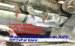
Underneath the rack I could see how to disconnect the exhaust pipe shield. There are two clips that just slide to either side , and then the plate can be removed.
Now it’s possible to see and unclip the wire clip that holds the pipe holder and 3 pipes to the top of rack unit.
attachment.php

Because of all the pipes and cables these simple procedures become difficult and time consuming.
Once removed, and all the pipes disconnected, you need to quickly plug the pipes or else even more LHM pours out on the ground. I used a short piece of plastic tubing plugged with a small plastic plug. This did the job.
The rack is held in place with 4 set screws, 13mm, two above and two below. The flexible coupling at the steering pinion is simple enough to undo. Once disconnected do not turn the coupling at all, or else you could put the control gears out of synch with the rack. This is apparently difficult to correct. As soon as the rack is disconnected it is recommended to put a pin through the pinion shaft to stop it from turning. I used a large screw with a plastic cap to keep it from falling out.
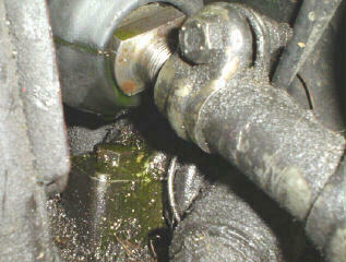
The tie rods have to be disconnected from the wheel/brake housing at the steering knuckle. Just undo the large nylock nut. You will have to hold the bolt still while undoing the nut, otherwise you will be there all day turning the nut while the bolt goes round with it. You will see that the lowest end of the shaft has two flat sides so you can grip it with a spanner or vice grip pliers. Once the nut and washer are off the shaft can be just pushed up and out.
Now the tie rods should be free of the wheel /brake unit.
In order to remove the rack, once everything was undone, you have to rotate the unit about 90 degrees so that the steering pinion is pointing upwards. This enables getting enough clearance to get it past the brake pedal unit, and out the side of the wheel arch.
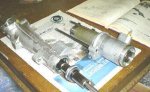
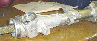
Once the rack is out of the car it’s simply a matter of giving it a good external clean with kerosene, and drying it. It’s amazing how nice and new it looks once the grease and grime is washed away. Carefully dismantle the whole unit, following the manual directions.
Have a good look for wear all around the hydraulic ram surfaces. Any sign of rust will mean replacement of the affected part.
The bearings will not come out until you remove the large o ring in either end. Some of these are deep inside the casings and difficult to get at. I ended up using two very sharp and pointed kitchen knives to grip and get under these o rings to remove them.
Lay all the seals and components out in order of removal and in the correct orientation. Clean out the casings thoroughly and dry them.
Find the matching seals from the replacement kit, and then one by one, dip them in LHM, then reassemble them in the places where the old ones came from.
Be very careful not to break them or force anything.
attachment.php

The manual just says to reassemble everything in the reverse order of disassembly. I found that to be an unintelligent method , because it would cause parts coming into contact with other parts that should not be in contact with each other.
I put both halves of the ram into their respective cylinders first, then assembled the piston, gently inserted the Teflon seal into it’s cylinder and finally put the rack-rod through the whole assembly last. This stops you from fouling one side of the ram with grease from the rack.
attachment.php


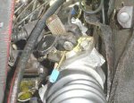
Once it’s all reassembled , It’s simply a matter of spending the best part of a day putting it all back into the car. Even knowing where everything came from and where it all should go will not save much time. It’s very awkward and difficult putting the large hydraulic pipe back in place with LHM dripping all over you , in your face , in your hair etc etc.
attachment.php


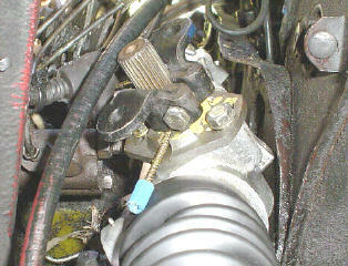
The rack, on it’s way back in going past the brake unit .

It’s all good fun, especially once it’s all done. The next job will be a wheel alignment. It’s possible to get it approximately right by sight, but the tyre guys have the gear to get it running true, with the toe in and toe out set correctly .
This job would not have been possible without the help of many and various members of AUSSIE FROGS who contributed helpful tips and hints. Those who had done this before were most helpful, and I thank them.

In Conclusion.
Now that I’ve reconditioned this power steering rack and seen the condition of the hydraulic ram I must say that I’m amazed at the quality of the engineering of these Citroen parts. I found no sign of wear on this 25 year old steering assembly. The only reason this rack leaked was because over time the rubber seals had become hardened and had worn down to the point where the LHM could escape. The Teflon rings and seals show no signs of wear and could have been re-used. In this instance I replaced all of them from the kit.
Cheers….George.
 

Attachments

  • Photo2.jpg
    Photo2.jpg
    25.5 KB · Views: 681
  • Photo3.jpg
    Photo3.jpg
    19.8 KB · Views: 785
  • Photo4.jpg
    Photo4.jpg
    12.7 KB · Views: 763
  • Photo5.jpg
    Photo5.jpg
    25.1 KB · Views: 935
  • Photo1a.jpg
    Photo1a.jpg
    20.5 KB · Views: 782
Ripper George,

More patience than me these days I can tell you.
I think I mentioned early in the piece that the only one we ever had out was years ago & that was when a motor was out and it is possibly a thing worth mentioning (although you have hinted at it) that the actual access would be far simpler if the engine was out of the car and in that case if someone had a reason to remove a motor for any other reason within a short space of time in teh future, say engine mounts or seals or something along those lines that this would be the time to do it. Not that it would speed the job up - say 3 hours to take engine out plus a day to reinstal, but could mean that overall time & trouble would be saved; just a thought.
I'd like to suggest that gibgib puts this in the Archives as I think it's too good a report to be just lost in cyberspace.
What's everybody elses opinions on that?
As I say 10/10


Alan S
 
Alan S said:
Ripper George,

More patience than me these days I can tell you.
I think I mentioned early in the piece that the only one we ever had out was years ago & that was when a motor was out and it is possibly a thing worth mentioning (although you have hinted at it) that the actual access would be far simpler if the engine was out of the car and in that case if someone had a reason to remove a motor for any other reason within a short space of time in teh future, say engine mounts or seals or something along those lines that this would be the time to do it. Not that it would speed the job up - say 3 hours to take engine out plus a day to reinstal, but could mean that overall time & trouble would be saved; just a thought.
I'd like to suggest that gibgib puts this in the Archives as I think it's too good a report to be just lost in cyberspace.
What's everybody elses opinions on that?
As I say 10/10


Alan S

Yeah,

bloody fantastic George. Finally we have someone that's got experiance pulling down the steering rack on the message boards. Every now and then somewhere there is a question about fixing the steering rack which is usually met with a universal :confused: :confused: 'cos no-one has ever needed to touch one before.

Certainly this is one for the archives before it's lost.

seeya,
Shane L.
 
Alan S said:
Ripper George,

More patience than me these days I can tell you.
I think I mentioned early in the piece that the only one we ever had out was years ago & that was when a motor was out and it is possibly a thing worth mentioning (although you have hinted at it) that the actual access would be far simpler if the engine was out of the car and in that case if someone had a reason to remove a motor for any other reason within a short space of time in teh future, say engine mounts or seals or something along those lines that this would be the time to do it. Not that it would speed the job up - say 3 hours to take engine out plus a day to reinstal, but could mean that overall time & trouble would be saved; just a thought.
I'd like to suggest that gibgib puts this in the Archives as I think it's too good a report to be just lost in cyberspace.
What's everybody elses opinions on that?
As I say 10/10


Alan S
Thanks Alan for your comments. I tried to send this to Gerry but it was too big , even after I broke it down and took out the photos.
The photos could be much better, I really had to reduce them to send them...and I could have taken more to illustrate more steps along the way. Also, I could not figure out how to place them where they should go , thus the comments...pic 1 here etc etc. And the Photos are not in the correct order at the bottom...I couldn't re-arrange them without deleting them.
Anyway, if anyone else has to do this it's not an impossible job to do. Removing the engine and gearbox is really not necessary, in fact I would hesitate to do that, that's a huge job. I'd only do that to replace a clutch or to do serious engine work.
My next article will be about how to replace seals and bearings in a seven piston pump. That should be even more fun.
Cheers...George. :cheers: :citroen:
 
DoubleChevron said:
Yeah,

bloody fantastic George. Finally we have someone that's got experiance pulling down the steering rack on the message boards. Every now and then somewhere there is a question about fixing the steering rack which is usually met with a universal :confused: :confused: 'cos no-one has ever needed to touch one before.

Certainly this is one for the archives before it's lost.

seeya,
Shane L.

Thanks for your nod of approval too, Shane. To my way of thinking , I just don't understand why the engineers in Citroen didn't put return pipes in the rack dust covers just the way the suspension covers do...so any leaks from the seals go back to the reservior. Once those seals go they really let the LHM loose. Air pressure and movement in the covers would not be a problem . Anyway, I guess they had their reasons.
It's just amazing engineering and quality.
So, I'm now one step closer to that roadworthy, but there's plenty more to fix up before that day comes.
Cheers...George. :cheers: :citroen:
 
A bit off topic to a point, but I'm sure Shane will agree with me, the job of pulling an engine on a CX is not the big deal it irst seems.
My son did one when he was about 16 and did it in 2 1/2 hours. He's since done it a couple of times & like all things, the first one is the worst.
That engine crane I posted about in the forum the other day is handy for that job & if ever you need to do lower engine mounts, you'll wish you had one. :cry: :cry: :cry: :confused:

Alan S :D
 
Alan S said:
A bit off topic to a point, but I'm sure Shane will agree with me, the job of pulling an engine on a CX is not the big deal it irst seems.
My son did one when he was about 16 and did it in 2 1/2 hours. He's since done it a couple of times & like all things, the first one is the worst.
That engine crane I posted about in the forum the other day is handy for that job & if ever you need to do lower engine mounts, you'll wish you had one. :cry: :cry: :cry: :confused:

Alan S :D
Hi Alan, I used one of those cranes many years ago when I did an engine changeover on my HD, or was it the HR? Anyway, they're a well designed tool that's for sure. They break down into seperate parts, so they go into the boot...tool hire companies hire them out.
If you had time it would be easy enough to build one , and you could use a bottle jack for the hydraulics. Pretty simple to do, just time consuming. And how often do you pull out a motor anyway?
Cheers...George. :cheers: :citroen:
 
We'd use one a few times a year. For instance, whenever you do a BX timing belt...ahh, heaven is......or if need to shift an engine or work on one where you need to push it around a bit or when connecting to an engine stand, load anything heavy onto the bench or trailer, move a dead car sideways in the garage, lift an outboard off a boat, fixing leaky sump gaskets without totally removing the engine.....you'd be amazed how often you use them when you have them & how much you miss them when it's not there.
At the current price of $249 you coulndn't even come close to building one yourself; think about it; forgetting the labour & specialised parts, what would 100 kgs of steel cost?

Alan S
 
Alan S said:
We'd use one a few times a year. For instance, whenever you do a BX timing belt...ahh, heaven is......or if need to shift an engine or work on one where you need to push it around a bit or when connecting to an engine stand, load anything heavy onto the bench or trailer, move a dead car sideways in the garage, lift an outboard off a boat, fixing leaky sump gaskets without totally removing the engine.....you'd be amazed how often you use them when you have them & how much you miss them when it's not there.
At the current price of $249 you coulndn't even come close to building one yourself; think about it; forgetting the labour & specialised parts, what would 100 kgs of steel cost?

Alan S

Alan,

I think the difference is not everyone else has a dozen or so cars around the place. In my case a father, brother & brother in law (amongst all the other cit-nuts around here) that want to borrow it. You have yourself and your kids that'll be using it all the time.

If you had one car, and no-one else that works on cars around the place, I could understand why you wouldn't want a crane.

Personally I've done enough motors with a bloody block and tackle off the shed rafters to never, ever want to pull a motor that way again. A 2cv may be an exception, as I can just chuck it's motor under one arm and carry it away :roflmao: :roflmao:

seeya,
Shane L.
 
George,

Very helpful!

A few points you might like to somehow work in before it is finalised and packed off to the Aussiefrogs technical archives:

* The coupling on the rack has a form of pointer and graduation markings for the eccentric adjuster. If you look closely at the lower plate, you will see a straight edge perpendicular to the shaft axis that 'points' out the location on the scale scribed in the edge of the upper coupling plate. It would be a good idea to initially set the coupling up to be half way to allow adjustment either way. You can see the marks and the pointer near the bolt marked 2 in Haynes pic 11.39.

* The control unit has a hole in it to allow you to lock it's internals in the straight ahead position. You are supposed to put a long pin in the hole filled by the small rubber stopper that has a tab on it. This locks the control unit in the straight ahead position. You really need to pull one apart to understand how and why this works. Note that the wheel and rack are always connected for safety, but the mechanism has 'slop' in it to allow the control unit to effectively operate as a feedback control device. It feels like something is broken when there is no LHM pressure, but this is normal. This 'slop' is why you can't adjust the tracking or alignment just by moving the wheel to the central position in a 'dead' car as you might in any other car. You need to remove the steering wheel and the control unit surround panel to get at this and insert the pin.

* To reconnect the rack and the control unit via the coupling, you need to put both in the straight ahead position and put the coupling on the most suitable splines. The pinion retaining plate has a slot to insert a rod (6.5mm) through the pinion to lock it in the straight ahead position. As the Haynes book suggests, you need to mark the position and orientation of the pinion retaining plate so you can reassemble it the same way. This allows the cutout in the splined section to match up with the bolt in the coupling. However, I wouldn't always assume it was correct when pulled apart since you don't know how many bodgers have been there before!

* Did you check the damper pad for the spring under the pinion housing. As I noted before, my rack had a broken cast iron pad that could have fouled the gear had it broken up and shifted.

* Point out that getting the tracking adjusted correctly is NOT the same as the wheel alignment. The alignment is to set up the toe in etc. while the tracking is adjusted via the eccentric in the coupling to set the relationship between the control unit and the rack. There is of course little point doing an alignment if there is any wear in the suspension/stering. Bottom ball joints in an earlier CX (before about 1979 build) are smaller than later cars and have a particularly hard life. Once the alignment is correct, you can then try the car on a flat straight section and adjust the eccentric through the RH front wheel arch in high position (using a stand for safety!) until it runs straight by itself (assuming the control unit is fine).

* Remove the locking pins before trying to drive the car unless you are up for a very rude surprise!!!

* Don't expect your local Bob Jane / Beurepaires / K-Mart to do an alignment. A lot of these guys are afraid the car might fall on them. Take it to a relaible Cit specialist or someone that really knows what they are doing.

Well done!

David

p.s. Possible problem with some of those Chinese hoists is that the legs may not go under a dead CX (and some other low slung cars) ?? You might remove the wheels, but then you have to roll the car back, so it's much like a block and tackle really.
 
David S said:
p.s. Possible problem with some of those Chinese hoists is that the legs may not go under a dead CX (and some other low slung cars) ?? You might remove the wheels, but then you have to roll the car back, so it's much like a block and tackle really.

Nah, this won't be such a problem. If the wheels are to small, they'll be a b@stard to wheel. You need to put a hydraulic cit on some lowish ramps before pulling the motor so you have access to underneath the car (to undo engine mounts etc ...).

seeya,
Shane L.
 
David S said:
David

p.s. Possible problem with some of those Chinese hoists is that the legs may not go under a dead CX (and some other low slung cars) ?? You might remove the wheels, but then you have to roll the car back, so it's much like a block and tackle really.

Nope; been there done that....they fit!! I actually used one to shift a CX that hasn't run for about 8 years; just picked it up in the air & walked it across my workshop floor.....sideways!! :eek: :D
As for the wheel alignment and seeing as the car is presently not registered, do like I do and DIY wheel alignment. Last one we did was taken to a "specialist" wheel aligner because my #1 son had just "invested" about 3 grand on wheels & tyres and reckoned he didn't want to risk getting them scrubbed. Reaction from specialist was "What did you want me to do? They're perfect!!" :confused: :confused:
It's a bit long winded but not hard & can be done deadly accurate.
I can post or PM the info if you require.

Alan S :adrink:
 
Alan S said:
As for the wheel alignment and seeing as the car is presently not registered, do like I do and DIY wheel alignment. Last one we did was taken to a "specialist" wheel aligner because my #1 son had just "invested" about 3 grand on wheels & tyres and reckoned he didn't want to risk getting them scrubbed. Reaction from specialist was "What did you want me to do? They're perfect!!" :confused: :confused:
It's a bit long winded but not hard & can be done deadly accurate.
I can post or PM the info if you require.

Alan S :adrink:

Hi Alan, please do. Or...why not post it for everyone to read?
Thanks...cheers...George.
 
David S said:
George,

Very helpful!

A few points you might like to somehow work in before it is finalised and packed off to the Aussiefrogs technical archives:

* The coupling on the rack has a form of pointer and graduation markings for the eccentric adjuster. If you look closely at the lower plate, you will see a straight edge perpendicular to the shaft axis that 'points' out the location on the scale scribed in the edge of the upper coupling plate. It would be a good idea to initially set the coupling up to be half way to allow adjustment either way. You can see the marks and the pointer near the bolt marked 2 in Haynes pic 11.39.

* The control unit has a hole in it to allow you to lock it's internals in the straight ahead position. You are supposed to put a long pin in the hole filled by the small rubber stopper that has a tab on it. This locks the control unit in the straight ahead position. You really need to pull one apart to understand how and why this works. Note that the wheel and rack are always connected for safety, but the mechanism has 'slop' in it to allow the control unit to effectively operate as a feedback control device. It feels like something is broken when there is no LHM pressure, but this is normal. This 'slop' is why you can't adjust the tracking or alignment just by moving the wheel to the central position in a 'dead' car as you might in any other car. You need to remove the steering wheel and the control unit surround panel to get at this and insert the pin.

* To reconnect the rack and the control unit via the coupling, you need to put both in the straight ahead position and put the coupling on the most suitable splines. The pinion retaining plate has a slot to insert a rod (6.5mm) through the pinion to lock it in the straight ahead position. As the Haynes book suggests, you need to mark the position and orientation of the pinion retaining plate so you can reassemble it the same way. This allows the cutout in the splined section to match up with the bolt in the coupling. However, I wouldn't always assume it was correct when pulled apart since you don't know how many bodgers have been there before!

* Did you check the damper pad for the spring under the pinion housing. As I noted before, my rack had a broken cast iron pad that could have fouled the gear had it broken up and shifted.

* Point out that getting the tracking adjusted correctly is NOT the same as the wheel alignment. The alignment is to set up the toe in etc. while the tracking is adjusted via the eccentric in the coupling to set the relationship between the control unit and the rack. There is of course little point doing an alignment if there is any wear in the suspension/stering. Bottom ball joints in an earlier CX (before about 1979 build) are smaller than later cars and have a particularly hard life. Once the alignment is correct, you can then try the car on a flat straight section and adjust the eccentric through the RH front wheel arch in high position (using a stand for safety!) until it runs straight by itself (assuming the control unit is fine).

* Remove the locking pins before trying to drive the car unless you are up for a very rude surprise!!!

* Don't expect your local Bob Jane / Beurepaires / K-Mart to do an alignment. A lot of these guys are afraid the car might fall on them. Take it to a relaible Cit specialist or someone that really knows what they are doing.

Well done!

David

Hi David, I locked the pinion, but I didn't adjust the tracking. I just removed the rack without ever touching or turning the control unit. The rack came out, and went back in in exactly the same position that it had been. I marked the positions of everything. There was nothing wrong with the relationship between the control unit and the rack, so I didn't change it.
I did however completely unscrew the track rods. I knew it was going to need a wheel alignment later, so I didn't worry about that.
Now that it's all back together, the steering returns to central just as it did before.
Now, I just need to correct those track rods.
Thanks for your help, and suggestions.
My report on the job I did was brief, and I left out some points that the manual covers in detail. I just commented on parts that the manual seemed to leave out, or not explain well enough.
Cheers...George.
 
George 1/8th said:
Hi Alan, please do. Or...why not post it for everyone to read?
Thanks...cheers...George.

I'll put it on a PM George as I have a feeling I'll spend the next fortnight refuting arguments from the sceptics who've never done one this way if I post it on a forum. :cry: :mallet:
It's so simple it's laughable and makes you wonder how the ones with the correct & expensive gear can get it so wrong so often. :confused:


Alan S
 
Alan S said:
I'll put it on a PM George as I have a feeling I'll spend the next fortnight refuting arguments from the sceptics who've never done one this way if I post it on a forum. :cry: :mallet:
It's so simple it's laughable and makes you wonder how the ones with the correct & expensive gear can get it so wrong so often. :confused:


Alan S
Ok...thanks Alan, I look forward to reading it. Cheers...George. :cheers: :citroen:
 
Yeah, well I'm brave enough.

I first did my own alignment because the specialist with the expensive equipment could get the toe in right but refused to even try and get the steering wheel spoke in the correct position (on my manual steered car). So I took it home and did it myself. I've done this at least 5 times in the last 15 years and haven't experienced any undue tyre wear problems.

We will assume that the front end is in good condition. Therefore, it is safe to assume that the castor and camber are OK. These are designed into the suspension geometry. The castor can be adjusted by moving shims on the bottom arm pivot but this is intended to allow for production tolerances and shouldn't ever need to be reset.

The CX should have 0-4mm toe in. Toe-in is where the front of the wheels are turned slightly in toward each other and is adjusted by screwing the tie rods on the end of the steering rack in or out. The toe-in should be measured on the centreline of the tyre surface. The toe-in is the difference between this centreline to centreline measurement when measured at the front and the back of the front tyres.

Because the body and engine are in the way we have to project the the wheel position down to the ground. I use a length of aluminium angle about 1200 long, the garage floor, a piece of chalk and tape measure. I mark both the angle and the tyres so that I can always use the same position to make the measurements. This effectively minimises any errors due to bent angles and uneven tyres.

With an hydraulic Citroen the wheel alignment has to be done with the engine running and the suspension at its normal height. The suspension geometry changes as the car moves up and down.

Hold the angle against the tyre so that it passes thru the driveshaft centreline with the end of the angle touching the ground in front of the wheel. Mark this point on the ground. Stick a bit of masking tape down and draw a line on that. Do the same to the rear of the wheel and also for the other side. Use a tape to measure between the marks front and rear. My piece of angle places the mark at about twice the normal wheel radius so if I get a measurement difference of between zero and 8 mm the alignment is within spec. Run the car up and down the drive between each measurement and adjustment just to be sure that the suspension is really settled in it's normal position.

I have always set my CX's up with zero to slight toe-in - but I am told that the the steering feels better with more toe in. I will try that next time.

This whole procedure just gets the wheels pointing correctly relative to each other. Adjusting the DIRAVI so that the car runs straight when you let go of the steering wheel is done by adjusting the cam on the steering coupling - and that is another story entirely.

Adjusting toe-in is not difficult nor all that critical. You can achieve good results at home using some care, a stick and a bit of chalk.
 
Rob T said:
The CX should have 0-4mm toe in.
Because the body and engine are in the way we have to project the the wheel position down to the ground.

My piece of angle places the mark at about twice the normal wheel radius so if I get a measurement difference of between zero and 8 mm the alignment is within spec.

Adjusting toe-in is not difficult nor all that critical. You can achieve good results at home using some care, a stick and a bit of chalk.

Thanks Rob, you have confused me with this bit...."My piece of angle places the mark at about twice the normal wheel radius so if I get a measurement difference of between zero and 8 mm the alignment is within spec."

I already thought that the wheels overall size from front to back as projected to the ground would be twice the radius. What do you mean by "my piece of angle places the mark at about twice the normal wheel radius". Why wouldn't it? Shouldn't the toe in still be 0-4 mm?
Thanks for the help anyway.
Cheers....George. :cheers: :citroen:
 
Status
Not open for further replies.
Top