DS - New alternator with voltage regulator

maxmaniac

New member
Tadpole
Joined
Oct 18, 2016
Messages
14
Location
Aveiro, Portugal
Hello all,

as I was having a bit of trouble with the original alternator + regulator combo on my DS23, I thought I would just buy a new 70A alternator with voltage regulator built-in.

Now the only problem is figuring out where is the D+ terminal on this thing... :blackeye:
B- and B+ terminals are identified in the plastic, but D+ is MIA.
I believe D+ would be the one with the flat terminal (green arrow on the picture), but there's also the possibility of being the round terminal (blue arrow), thus using an eye terminal.

What do you guys think?
Thanks everyone!
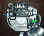
alternator.jpg
 
Blue seems to be ground.

Green would seem to be ign switched 12v+ via an indicator lamp.

Knowing the make and model would helpful.
 
Hello all,

as I was having a bit of trouble with the original alternator + regulator combo on my DS23, I thought I would just buy a new 70A alternator with voltage regulator built-in.

Now the only problem is figuring out where is the D+ terminal on this thing... :blackeye:
B- and B+ terminals are identified in the plastic, but D+ is MIA.
I believe D+ would be the one with the flat terminal (green arrow on the picture), but there's also the possibility of being the round terminal (blue arrow), thus using an eye terminal.

What do you guys think?
Thanks everyone!

View attachment 95976


Forget the green is an earth just connect the B+ to the positive side of the battery and the green lug goes to the dash light remove all other wires they are now obsolete, good move these alternator works very well and the dash light governs the charging command. Easy installation
 
Forget the green is an earth just connect the B+ to the positive side of the battery and the green lug goes to the dash light remove all other wires they are now obsolete, good move these alternator works very well and the dash light governs the charging command. Easy installation


Isn't it the blue arrow ground ?

And the green arrow is the "dash lamp" ?

The colours chosen are just arbitrary .
 
Blue seems to be ground.

Green would seem to be ign switched 12v+ via an indicator lamp.

Knowing the make and model would helpful.

Hello robmac, unfortunately, I can't tell the make nor model as it has no references anywhere.
In fact, it has no references but came with a small testing report detailing the conditions and values regarding rpm, output and losses; still no wiring instructions or something identifying its terminals :D
All I can tell you is that it's from franzose.de (if I may write it here)
Thanks for your input!


Forget the green is an earth just connect the B+ to the positive side of the battery and the green lug goes to the dash light remove all other wires they are now obsolete, good move these alternator works very well and the dash light governs the charging command. Easy installation

Hi Le Parisian,
I do know I only need two wires (the large one goes to B+ terminal and the smaller one from the dash light connects to D+), but thanks for stating it again as it reassures what I was about to do!
You got me a bit confused with the colors, though :wink2:
I believe I should discard the blue arrow and use the green one as D+, correct?
I was inclined to do so, but just wanted to make sure before I set something on fire (which wouldn't be perfect...) :D
Thanks for your reply!
 
Just leaving this here for someone with the same doubts as me:

--> D+ is indeed the flat terminal (green arrow on the previous picture)
 
Hoping I will get a response to this old thread.

I am looking at purchasing one of these units to replace my failing Ducellier setup. I am confused by D+. What wire are you referring to? My Ducellier has +, EXC and IND. Am I correct in assuming + will go to B+, EXC is no longer required, and IND is the D+.

Once fitted should I disconnect, or would it be okay to leave, the existing connections to the regulator?

Many thanks.
 
Thanks for that, but I am afraid I struggle to follow those wiring diagrams - all wires seem to disappear into a harness never to be traced again. I can clearly see the D+ on the alternator in the display, but that is not evident on the picture earlier in this thread. I think I need a step by step "for Dummies" when it comes to auto electrics.
 
you keep the black and yellow sleeve wires hook them up to new alternator and isolate the white one.

and Bob's your transvestite auntie. Not the bob btw.
 
Ha ha. Thanks for that. I translated your "cheat sheet" into English and get the picture. Slow learner!!

Cheers
 
Well I have followed the "cheat sheet" to the letter, and my new alternator does not charge. The yellow light comes on and stays on, and there is no charge across the battery terminals.

This is what I have done on the alternator: Black to B+, Yellow (exc on original) to the spade terminal (green arrow in picture below), and disconnected white (ind on original).

Then, not mentioned above, but in the "cheat sheet", on the regulator I disconnected yellow (exc) and Red (L) terminals and joined them together. Disconnected purple (bob) and white (R) and isolated them.

Nada, nothing, no charge. Please help!
95976d1493921272t-ds-new-alternator-voltage-regulator-alternator.jpg
 
Hi Errol_S,
I'm at work at the moment, but from what I remeber, forumnoreason's reply is the correct one.
Also, the alternator on my DS only starts charging after 1500 rpm (on the engine), perhaps you should try to rev the engine a bit and see if the situation changes.
In any case, in a couple of hours I can see how I connected everything on mine and I'll share with you.

Regards!
 
Hello, probably irrelevant, is the warning bulb an ordinary incandescent type or an LED? The excitation of the charging circuit uses the current through the bulb, so an LED type won't work (it only allows current one way, you need two way). A decent amount of revs can cause self excitation.
Then again, some alternators are self exciting.
 
Thanks for responding Maxmaniac - hopefully your previous experience will solve my dilemma. Badabec the bulb is stock standard incandescent. I just wonder why the B- on the new alternator had a loose fitting nut, as if it was expecting a terminal to be added. I also find it strange why the B- is insulated from the body of the alternator if it is meant to be grounded. Scared that I might blow a diode (and my money) if I do connect an earth to B-.

Currently blowing my freaking mind with Annie. Named orphan Annie because she was found under a tree and no one wanted her. Should have left her there!!!

Thanks all for the advice.
 
Hello there,
I just read the thread more closely and the link forumnoreason gave (with french instructions) is the guide I followed back then.
As the insulation tape was falling apart in my car, I just removed the EXC yellow J11 wire from the installation and connected the red R3 (now using a flat terminal) from the regulator directly to D+ on the alternator.
The black N2 terminal (big round terminal) is connected to the B+.

alternator2.jpg

Hope this helps!
 
two things, is battery low or flat and does your car have a starter relay on the battery?

I think you should contact Child Protection agency to sort Annie out.
 
Thanks Maxmaniac. That is essentially what I have done by joining regulator exc and L - maybe worth running L (R3) directly.

Forumnoreason I think I will contact an adoption agency rather. But in answer to your two questions:
* The battery is fully charged at 13.6V
* Yes I do have a starter relay on the battery

Cheers
 
I surmise from your description of the yellow light coming on and staying on (even with the key off) is that your car has a BVH transmission and what you have done is to stumble onto the infamous BVH starter interlock problem.

There are only two connections necessary for the aftermarket alternator to work. The battery connection (M6 post) and the indicator light (which also provides the initial excitation for the alternator to wake up). To avoid having to splice a wire from the indicator light (L) to the alternator, the cheat sheet commandeers the "EXC" wire to extend the L wire to the alternator. You appear to have done everything correctly, except, you have failed to disable the BVH starter interlock, which is causing the alternator to ground through the ignition switch when the key is off.

You need to disconnect the ground wire from the wand and provide an independent ground, so that the wand is no longer trying to ground through the (high impedance) lamp connection on the alternator. Once you do that, all will be as it should, except the starter lockout will be disabled, so you will have to be careful not to engage the starter with the engine running. If the alternator has a square wave tachometer output, you can restore the starter interlock by wiring in a common DIN relay.

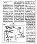
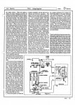
The whole starter interlock issue is explained below:

voltage regulator article A2_Page_1.jpgvoltage regulator article A2_Page_2.jpg
 
Top