
You are using an out of date browser. It may not display this or other websites correctly.
You should upgrade or use an alternative browser.
You should upgrade or use an alternative browser.
69 404 restoration
- Thread starter Dano
- Start date
I took two of my car's three horns apart and they didn't work when I put them back together. They were not working all that well before either. I will have a look at that adjustment too. I had been planning to just replace the lot of them with modern horns.
I took two of my car's three horns apart and they didn't work when I put them back together. They were not working all that well before either. I will have a look at that adjustment too. I had been planning to just replace the lot of them with modern horns.
Mike,
I watched a YouTube video last night, that I think will help. Will try what it suggests on Sunday. Full day of granddad duties today.
It has to be something to do with tensioning of the diaphragm via the screw on the back.
Cheers,
Dan
The horn now works.
It had me stumped! Circuits correct, no shorting and tested as per Youtube video posted in an earlier entry.
Every time it was bolted together, the diaphragm stopped vibrating. Deduced it had to be an earthing issue, somewhere/somehow. Nope. Pulled apart and reassemble at least three times.
The only thing not changed was the diaphragm. It’s spring steel, surely it can’t be that! Out of frustration, another was removed out of a spare none working horn.


Immediate success with minor tuning required. Go figure, as my daughter would say. It just doesn’t make sense to me.
No silicon was used in the assembly, just gasket paper. This means I will have to run a bead around the joint to protect the paper from water ingress and then give it a final touch up and repaint.
Call me peDANtic, but I wasn’t going to let something as simple as a horn stump me.
Cheers,
Dano
It had me stumped! Circuits correct, no shorting and tested as per Youtube video posted in an earlier entry.
Every time it was bolted together, the diaphragm stopped vibrating. Deduced it had to be an earthing issue, somewhere/somehow. Nope. Pulled apart and reassemble at least three times.
The only thing not changed was the diaphragm. It’s spring steel, surely it can’t be that! Out of frustration, another was removed out of a spare none working horn.
Immediate success with minor tuning required. Go figure, as my daughter would say. It just doesn’t make sense to me.
No silicon was used in the assembly, just gasket paper. This means I will have to run a bead around the joint to protect the paper from water ingress and then give it a final touch up and repaint.
Call me peDANtic, but I wasn’t going to let something as simple as a horn stump me.
Cheers,
Dano
It looks a lot better than when it left my place... but it doesn't sound like a 404 horn, more like a Mazda... Try winding the adjuster up a bit!The horn now works.
It had me stumped! Circuits correct, no shorting and tested as per Youtube video posted in an earlier entry.
Every time it was bolted together, the diaphragm stopped vibrating. Deduced it had to be an earthing issue, somewhere/somehow. Nope. Pulled apart and reassemble at least three times.
The only thing not changed was the diaphragm. It’s spring steel, surely it can’t be that! Out of frustration, another was removed out of a spare none working horn.
View attachment 124286 View attachment 124287
Immediate success with minor tuning required. Go figure, as my daughter would say. It just doesn’t make sense to me.
No silicon was used in the assembly, just gasket paper. This means I will have to run a bead around the joint to protect the paper from water ingress and then give it a final touch up and repaint.
Call me peDANtic, but I wasn’t going to let something as simple as a horn stump me.
Cheers,
Dano
It looks a lot better than when it left my place... but it doesn't sound like a 404 horn, more like a Mazda... Try winding the adjuster up a bit!
Cheers Bruce,
The casing is my original, it was the diaphragm out of your old none working horn that I used.
Dano
This could have quickly ended in tears!


Insert any expletive you wish, as I am sure that I used all of them within a few seconds.
A timely reminder to all, remove the positive wire from the battery when working in and around the engine bay.
The NOS quick release battery terminals have paid for themselves already.

The damaged was caused when I drop a spanner, whilst tightening the brake line unions on the booster. The spanner shorted between the power terminal on the starter motor and the positive terminal on the voltage regulator.
It could have been a lot worse, so I’m counting my lucky stars. Just so fortunate that it was confined to one small loom and not a complete under dash melt down.
As a precaution, the whole loom will be re-fabricated.
It is pinned out and ready to go on Friday.

I'll just put it down to a character building.
Cheers,
Dano
Insert any expletive you wish, as I am sure that I used all of them within a few seconds.
A timely reminder to all, remove the positive wire from the battery when working in and around the engine bay.
The NOS quick release battery terminals have paid for themselves already.
The damaged was caused when I drop a spanner, whilst tightening the brake line unions on the booster. The spanner shorted between the power terminal on the starter motor and the positive terminal on the voltage regulator.
It could have been a lot worse, so I’m counting my lucky stars. Just so fortunate that it was confined to one small loom and not a complete under dash melt down.
As a precaution, the whole loom will be re-fabricated.
It is pinned out and ready to go on Friday.
I'll just put it down to a character building.
Cheers,
Dano
Attachments
Last edited:
This could have quickly ended in tears!
View attachment 124331 View attachment 124337 View attachment 124333View attachment 124334View attachment 124336
Insert any expletive you wish, as I am sure that I used all of them within a few seconds.
A timely reminder to all, remove the positive wire from the battery when working in and around the engine bay.
The NOS quick release battery terminals have paid for themselves already.
View attachment 124338
The damaged was caused when I drop a spanner, whilst tightening the brake line unions on the booster. The spanner shorted between the power terminal on the starter motor and the positive terminal on the voltage regulator.
It could have been a lot worse, so I’m counting my lucky stars. Just so fortunate that it was confined to one small loom and not a complete under dash melt down.
As a precaution, the whole loom will be re-fabricated.
It is pinned out and ready to go on Friday.
View attachment 124335
I'll just put it down to a character building.
Cheers,
Dano
It could have been prevented if
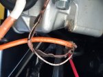
This could have quickly ended in tears!
View attachment 124331 View attachment 124337 View attachment 124333View attachment 124334View attachment 124336
Insert any expletive you wish, as I am sure that I used all of them within a few seconds.
A timely reminder to all, remove the positive wire from the battery when working in and around the engine bay.
The NOS quick release battery terminals have paid for themselves already.
View attachment 124338
The damaged was caused when I drop a spanner, whilst tightening the brake line unions on the booster. The spanner shorted between the power terminal on the starter motor and the positive terminal on the voltage regulator.
It could have been a lot worse, so I’m counting my lucky stars. Just so fortunate that it was confined to one small loom and not a complete under dash melt down.
As a precaution, the whole loom will be re-fabricated.
It is pinned out and ready to go on Friday.
View attachment 124335
I'll just put it down to a character building.
Cheers,
Dano
It could have been entirely avoided if fusible links had been installed
")
Robmac,
You are right.
We had discussed inserting one earlier and it was on the to do list. Will be the first thing done after the repair. I'll do it as per your drawing.
Cheers,
Dan
You are right.
We had discussed inserting one earlier and it was on the to do list. Will be the first thing done after the repair. I'll do it as per your drawing.
Cheers,
Dan
Robmac,
You are right.
We had discussed inserting one earlier and it was on the to do list. Will be the first thing done after the repair. I'll do it as per your drawing.
Cheers,
Dan
I respectfully suggest you fit an insulation boot on starter main battery terminal as well.
Something this perhaps https://www.ebay.com.au/p/135058097...843303011&targetid=925038216461&device=c&mkty
Woah, close call! It recalls one occasion when I had a weird meltdown in the steering column loom of my first 1967 404C - super hot wire, the car was operating, burnt all the insulation off but luckily didn't catch fire. I never did figure out what caused it.
With modern wire, make sure it's not got that godawful soy-based insulation.
With modern wire, make sure it's not got that godawful soy-based insulation.
With modern wire, make sure it's not got that godawful soy-based insulation.
I use a marine grade wire which is pre-tinned. Makes it a lot easier when soldering terminals, prevents burn back when soldering. Soy based insulation? Yuk, just like soy milk.
is that why rats eat it ,i recently had 5 wires in a loom completely disappear threw rats ,,not chewed completely gone ,i had to solder sections in and insulate ,i use those wax block baits wired onto battery terminals so they cant take off with them ,shewed through the windshield washer hose under the bonnet ,they must like the taste ,pugs
New wiring loom fabricated and installed. Two, 40-amp fusible links were installed to help prevent future meltdowns. One on the power wire between the alternator and starter motor and the other on the main power supply wire to the main fuse box.
Thanks for your advice ROBMAC.

The bonnet and boot lids have been installed and aligned. The boot, door and glove box locks have all been keyed alike. A NOS bonnet pin mechanism was used.

Still waiting on Germany to re-open its international mail services, so I can receive the following new bits. Bonnet release cable, number plate light seal and light stalk.
Bit of a walk around video.
Tomorrow, the interior C pillar upholstery pads will be installed, followed by the polishing of the bumper bars and a few missed door trims.
The right rear door needs a little remedial work before it can be hung.
Thanks for your advice ROBMAC.
The bonnet and boot lids have been installed and aligned. The boot, door and glove box locks have all been keyed alike. A NOS bonnet pin mechanism was used.
Still waiting on Germany to re-open its international mail services, so I can receive the following new bits. Bonnet release cable, number plate light seal and light stalk.
Bit of a walk around video.
Tomorrow, the interior C pillar upholstery pads will be installed, followed by the polishing of the bumper bars and a few missed door trims.
The right rear door needs a little remedial work before it can be hung.
Despite not yet being finished, it looks amazing. It's a real bugger about the wiring. I think we've all dropped tools which have caused a few sparks. Fortunately, I've been lucky enough to avoid burnt wiring.
Hey Dan that's 'looking pretty sharp, the last time I saw the little taka in the flesh he was just a partly repaired shell. Very well done indeed. Keep going Lad you are nearly there. Kudosness. 
Looking good.
Germany's international mail service was fine for me when I got the new camshaft about a month ago. Has there been a change since?
Germany's international mail service was fine for me when I got the new camshaft about a month ago. Has there been a change since?
The last couple of days were spent fabricating and installing the trim for the C pillars and the rear parcel shelf. This was followed by applying felt trim into the boot area.
The C pillar trims had to be made first, as the bottom edge of the vinyl is glued to the metal frame of the parcel shelf.
New pillar panels were traced onto and cut out of 2mm ply. To obtain the correct curvature, the ply was soak in water to make it more flexible, then it was clamped into place and allowed to dry in situ, thus allowing them to form the correct shape. 9mm foam was used as the cushioning.


The vinyl for the rear parcel shelf is attached to a stiff fibrous 3mm cardboard panel. This was done in two sections. The flat shelf piece and the rear curved section that follows the rear curve of the shelf and the convex curve of the rear windscreen. Paper patterns were made for each section, then traced onto the cardboard. The shapes were tapped together with cloth tape on both sides. The vinyl was attached as one-piece using 3M, 77 adhesives.


The 3mm felt boot trim was a little more difficult. This was due to the various curved surfaces and levels of the rear-axle housing. As with the parcel shelf, various patterns were drafted. These were mainly done with paper and masking tape. The paper was moulded as best as possible, then masking tape was used to finish the shape. The profile was outlined with a pen and then the paper and tape were carefully removed. The pattern was laid on the bench, with the sticky side of the tape up. More tape was applied over the original tape to give it strength and to prevent the tape getting stuck to other objects. The excess tape was trimmed along the pen lines. After tracing onto the felt, the pieces were cut and trial fitted. When gluing the panels into position, pieces of PVC conduit etc, were clamped into the curved strengthening profiles to achieve the same profile within the felt.


Although, it was not fitted originally, I attached a piece of felt to the underside of the boot lid. This to help prevent the lid from being dented outwards, when closed on objects within the boot. My ’70 had many.
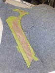
The paper pattern layout is for the floor carpet.
The tracing and taping technique, was something I picked up from the web, when re-covering the seat on my son’s ’74 Iron Head Harley.
The C pillar trims had to be made first, as the bottom edge of the vinyl is glued to the metal frame of the parcel shelf.
New pillar panels were traced onto and cut out of 2mm ply. To obtain the correct curvature, the ply was soak in water to make it more flexible, then it was clamped into place and allowed to dry in situ, thus allowing them to form the correct shape. 9mm foam was used as the cushioning.
The vinyl for the rear parcel shelf is attached to a stiff fibrous 3mm cardboard panel. This was done in two sections. The flat shelf piece and the rear curved section that follows the rear curve of the shelf and the convex curve of the rear windscreen. Paper patterns were made for each section, then traced onto the cardboard. The shapes were tapped together with cloth tape on both sides. The vinyl was attached as one-piece using 3M, 77 adhesives.
The 3mm felt boot trim was a little more difficult. This was due to the various curved surfaces and levels of the rear-axle housing. As with the parcel shelf, various patterns were drafted. These were mainly done with paper and masking tape. The paper was moulded as best as possible, then masking tape was used to finish the shape. The profile was outlined with a pen and then the paper and tape were carefully removed. The pattern was laid on the bench, with the sticky side of the tape up. More tape was applied over the original tape to give it strength and to prevent the tape getting stuck to other objects. The excess tape was trimmed along the pen lines. After tracing onto the felt, the pieces were cut and trial fitted. When gluing the panels into position, pieces of PVC conduit etc, were clamped into the curved strengthening profiles to achieve the same profile within the felt.
Although, it was not fitted originally, I attached a piece of felt to the underside of the boot lid. This to help prevent the lid from being dented outwards, when closed on objects within the boot. My ’70 had many.
The paper pattern layout is for the floor carpet.
The tracing and taping technique, was something I picked up from the web, when re-covering the seat on my son’s ’74 Iron Head Harley.
Attachments
Last edited: