performance 8v cylinder head build

chez00

Active member
Fellow Frogger
Joined
Nov 26, 2010
Messages
570
Location
Adelaide
I'll be working on this over the next few months after hours. It might not interest many but I know a few will like it, so here goes:


The Plan:
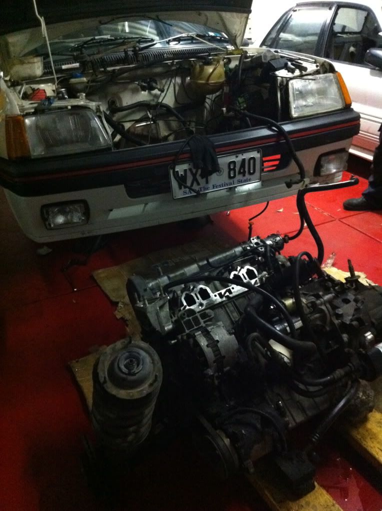
I own a series 1 205 Gti with the DFZ 1.9l in it. I’ve had it for nearly four months now and as most of you would know who own one, they really are great cars. I love it and choose to drive it over and above my other ride, an evo 7, more often than not.

The thing drives great, is clean and I reckon it probably has one of the best original interiors going around: all the electrics work (now), no tears or cracks or anything. I even have the original books and the tape deck which will go back in soon.

The throttle response is excellent and is the first thing I noticed when I drove it for the first time. The DFZ leaves you wanting in power though and that was what prompted this project.

I want to keep it street so I don’t want a dyno queen or a stripped out track mongrel: just a good torquey car that I can surprise a few people off the line with, and go out to an occasional track day without getting too far left behind.

The first and most glaring problem to address is the shockingly low compression. 8.4:1 would be well suited to a forced induction set-up but I really don’t want to go down that road – I love the sound and throttle response of a nicely tuned naturally aspirated engine so decided to travel that road.

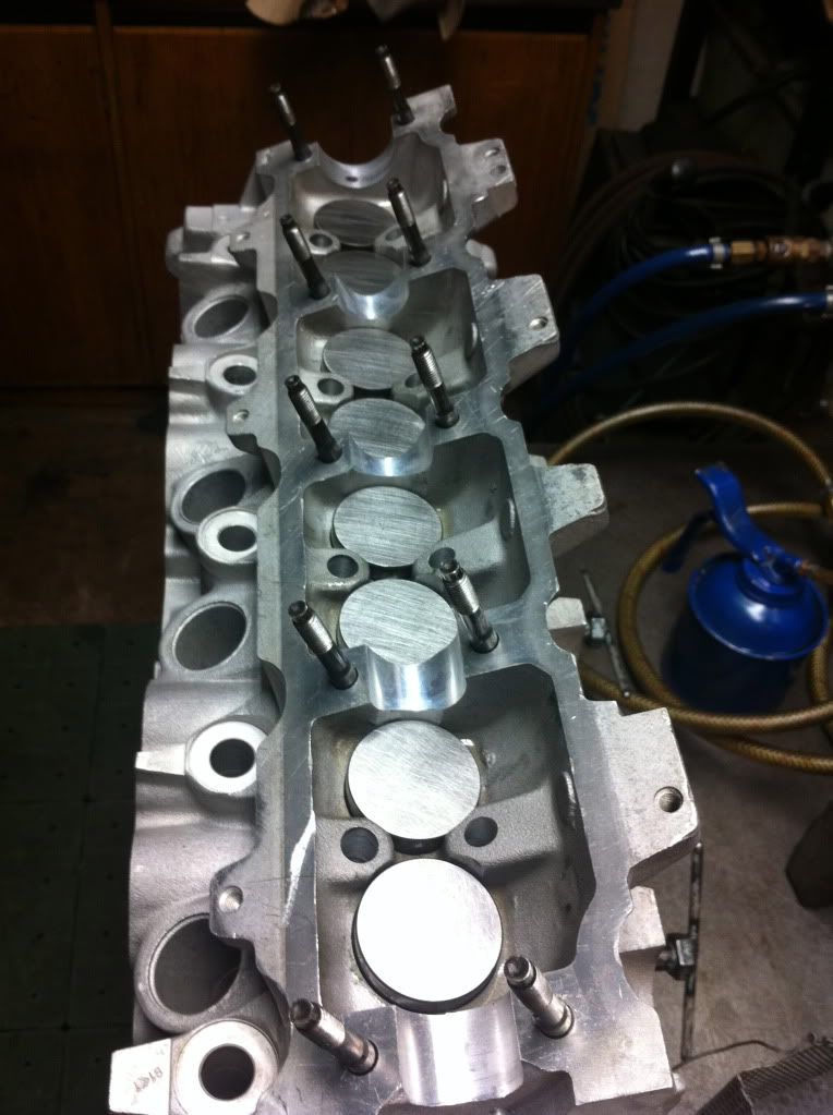
Thanks to the very helpful info provided by some Aussie Froggers, I found out the series 3 GTi’s (and the 1.6’s) had the DKZ high compression engine: the cylinder head had smaller chambers raising the compression ratio to 9.2:1. If you bolt one of these onto the DFZ bottom end it jumps the CR to somewhere around 10.5:1 due to the smaller dishes in the pistons of the DFZ.

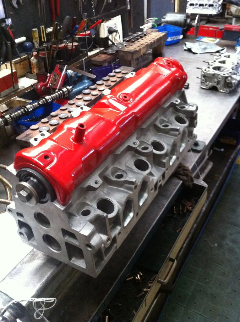
I have the rare opportunity to use a fully equipped machine shop after hours (I’m a final year apprentice of Automotive Machining in my family business) so for me the most economical way to extract power is through a nicely thought-out cylinder head build. The only cost would be in the parts used.

After some thought I decided I’d perhaps try and contribute some quantitative evidence for or against ‘big-valve heads’ (BVH) for the XU9 8v. My dad made a pretty nice flow bench that we use in the shop every now and then usually for in-house development on certain cylinder heads. Although it is pretty well-calibrated, I reckon the only real way to come up with absolute figures that are genuinely comparable would be for me to compare a stock valve head to a BVH on the same bench. Stage 2 of this project, which will be a complete rebuild, will also include some pretty extensive testing on our engine dyno, once again comparing actual power outputs of any modifications.

I subscribe to the idea that it is most helpful to view an engine as an air pump. The more air the engine can pump per RPM the more ‘efficient’ it is in making power. So obviously big inlet valves are going to help if you subscribe to this theory. I’m also aware though, that this can be overly simplistic and there are a variety of variables such as entry angles, swirl, turbulence and very importantly velocity that all come into play. The classic old-school example is that a Holden 253 without any other modifications runs better and makes more power with the stock heads than with the 308 big valve/port heads, all because of air speed.
 
The Head:
So down to the cylinder head in question.
IMG_0201.jpg

I bought it off a Frogger who had changed direction with his own build. First I pulled it apart, chemical cleaned and bead blasted the head (as you can see in the pic above) to get a closer look at the condition. The head is in reasonable nick with only a few bits of corrosion that I’d tidy up. The camshaft tunnels were straight and in good condition. I then crack and hard tested it to make sure it was a suitable base, which it passed. All in all a good base for a high performance head.
IMG_0219.jpg

The valve guides in it were probably passable although there was a little too much play in the exhaust valve guides for my liking. Because I was going to press them out for some initial port work anyway, I decided I would fit new ones. I took a measurement of how far the guides protrude from the head before pressing them out.
 
Port matching: After pressing the guides out
IMG_0202.jpg


I matched up the inlet and exhaust gaskets to the ports.
IMG_0225.jpg


This is something you could do at home if you have a dremmel or die-grinder. The idea is to use some white-out or preferably metal marking ink as I’ve used, and paint the manifold face of the ports. Then line up the (new) manifold gaskets with the bolt-holes, and scribe the outline into the paint with a sharp object. You then know that if you grind out this shape on the head and manifold, it will all line up nicely and ensure less inhibited flow into your engine.

Afterwards I did some initial shaping, mindful of not wanting to take any material out unnecessarily. The only thing I really did was reshape the ‘well’ in front of the valve guide boss on the inlet side (a small dip before a sudden rise can hinder flow), and eliminate any casting lines and imperfections (all of which you can see in the picture below). Note that I didn't hack out the 'shoulders' of the port to exactly match the shape of the gasket. The existing shape with the channel down the centre was retained. Note also that I've done nothing around the valve seat or short side radius (SSR) - two very sensitive areas that can only really be altered with the assistance of a flow bench.


IMG_0221.jpg


Further quantifiable alterations could be made later with the assistance of the flow bench. I semi-finished the ports with a fine stone and then by hand with 120-grit emery tape.


IMG_0253.jpg


IMG_0269.jpg


IMG_0270.jpg


I'll finish off once the flow bench data is dealt with.
 
Valve Guides, Welding:
Next I chose a correct tool to press my new guides in.


The inlet and exhaust guides are different lengths but the top end where the stem seal presses on are identical. You need to be careful not to damage the guides here as the bronze is quite thin and brittle.

IMG_0376-1.jpg


If you just bashed them in with a pilot you’d risk shattering a guide or three. You can see in the picture that the pilot I used had been turned up on the lathe to allow the contact surface to rest on the ‘shoulder’ of the guide, while the thinner section sits inside the pilot with no pressure applied.


IMG_0379.jpg


Before pressing the guides in I thought I better do the welding. No use distorting my new guides unnecessarily. Sometimes you’d get away with skimming a bit more off the face on the mill to clean up minor pock-marks, but I really don’t want to bump the compression ratio up any further, so I thought the best approach would be to weld the corrosion out.

IMG_0371.jpg


I die-grinded out the corrosion that I thought was a threat of compromising the head gasket (see how it's sitting just outside the gasket compression ring). In preparation for welding I baked the head to 150 degrees Celsius, and TIG welded the repair sections. If you don’t pre-heat the head the welding is much more difficult and you end up ‘crystalising’ your weld.


IMG_0390.jpg


While the head was still at temperature I fitted it to the straightening jig and allowed it to cool slightly, ensuring that the head would resettle straight by measuring through the cam tunnel with a straight edge and feeler gauges.


IMG_0383.jpg


While the head was still warm (hot to the touch but bearable), I placed it on the press and pulled my new guides out of the freezer. Using a 7.5mm spacer between the head and the pilot (the correct protrusion), I pressed all of them in. Obviously a warm head and cold guides assist in pressing them in smoothly without stressing the parent bores in the head.

Guides like this are ‘semi-finished’, meaning the valves won’t drop straight in – the holes are around 7.9mm. The manufacturers do this because there’s a likelihood the guides will distort when you press them in. So the next job was to rig the head up on the cylinder head machine and drive a 8mm reamer through the guides.


IMG_0392.jpg


With performance applications, guide clearances become crucial. If I have too much clearance between the valve stem and the guide, all sorts of problems occur. Oil will creep down through the guides into the combustion chamber, causing smoke, clogged spark plugs and a lack of power. Also, over 60% of the heat in a valve is transferred through the valve guide to the cylinder head, so the clearance can’t be too large otherwise you start burning out valves.

Too little clearance and the valve risks ‘nipping’ - where the valve expands as engine temp comes up, and creates an interference fit in the guide. Because the clearance is too small, no oil gets through between the guide and the valve. It then has so much friction that it overcomes the pressure of the valve spring and jams open. If this happens, bye-bye piston, valve, valve guide and probably conrod and crankshaft if it occurs at high RPM (Murphy says it will).

So to ensure I have the right clearance, I measured the guide’s top, middle and bottom with a ball gauge. I then measured the valve stems of the (new) valves I will be using and subtracted the latter form the former. I had .0019 - .0021” clearance across the guides, which is about right (.0015-.003” or .038 - .076mm is rule of thumb for new 8mm guides, tending towards the larger size for exhaust). Sorry for the imperial measurements, most of our tooling and machinery is imperial.


Reaming, although accurate, can leave a rough finish inside the guide. So I then passed a diamond flex-hone through the guides.


IMG_0393.jpg


This little brush is coated in diamonds which give the inside diameter (ID) a beautiful ‘crosshatch’ much like that in a newly honed piston bore. This allows the guide to hold oil while still having a relatively tight clearance. It is small things like this that makes the difference between an average engine and a performance one. Every bit of friction reduced enhances the mechanical efficiency of my engine. I used the hone to finish all the exhaust guides to .0022” clearance and the inlets to .002".
 
Geez....

Half your luck if you have the skills and machinery. This is a really good read.


Chris
 
Cheers Chris looks like your build's coming along nicely.

I got some parts on Friday:

IMG_0399.jpg


IMG_0398.jpg


A water pump, timing belt, tensioner and head bolts. The exhaust valves that came with the head were for some reason all bent, so I got replacement ones of those (standard 34.5mm). The inlets that came with the head were all fine, and measured 41.6mm on the head. The stems were slightly worn but I don’t think I’ll be using them unless flow bench results surprise me. So I purchased a set of 43mm inlet valves as well, with larger valve seat inserts to suit.


IMG_0229.jpg


The new 43mm valve is in the vise, with the old 41.6mm valve sitting on top.

These new valves were actually to suit a Mercedes – the stem is super long so I will need to trim it, re-cut a collet groove and heat treat the valves.


IMG_0230.jpg


This (at least for me) will be a lot cheaper than ordering custom valves from the UK or something, considering all four costed me just $36 for a high quality Mahle valve. The extra 1.4mm on the head gives me around 6.5% more surface area and thus potential for around as much gain in power over a stock valve if you follow through on the logic. So my 110hp engine if I did nothing else, has potential for 117 hp.

My next job is to select an appropriate camshaft so that I can set my lift limits on the flow bench. I might do a write-up on considerations when selecting a cam as this is all fresh in my head from my latest stint at trade school.
 
Peter is pretty switch on with cams for 205GTIs.

Try chatting with him first.


Chris
 
chezOO,
A great read indeed, something you could publish and sell.
Any words of caution with the installation of bronze guides ie the necessity of a proper engine warm up?

Oh, it must be great to have a Dad like yours.
 
chezOO,
A great read indeed, something you could publish and sell.
Any words of caution with the installation of bronze guides ie the necessity of a proper engine warm up?

Oh, it must be great to have a Dad like yours.
Thanks very much Wildebeest. There are certainly perks to having a dad with a very nicely decked out machine shop.

To be honest I'm working in the dark a little on this project as I am yet to get my hands on a factory 205 workshop manual (if anyone could steer me in the right direction that would be awesome). I'd kill for one, and I'd love to know what the guide clearances are as specified by the factory, along with a long list of other technical specifications that Haynes don't provide.

I've never heard of any unique requirements for warm-up with bronze guides but that doesn't mean that there aren't different procedures (have you heard of any?). As mentioned above, I'm an apprentice not a guru by any stretch of the imagination. The only thing my dad's told me is that bronze has good natural lubrication and oil retention properties so can run tighter clearances than, say, a cast iron guide. You see them mostly in European cylinder heads. I know Porsche tuners run very tight clearances in certain applications - half the factory recommended clearance of .002". I thought I'd err on the side of caution with my clearances.
 
chezOO,
In preparing a Volvo B23 engine for the Repco Round Aus Trial in 1979
The head was sent away, Melbourne, for some extensive work.
This included bronze valve guides. The instructions given with the head was to gradually warm the engine to allow the bronze guides to expand gradually with the alloy head or run the risk of the guides dropping out.
Of course this is over 30 years ago, things may have changed since then.
 
A quick update -
I've stalled due to a clutch cable replacement (very difficult to locate!) and doing up another car I own to sell, but am now back on track. I got the opportunity the other day to cc the chambers of my cylinder head:
IMG_0409.jpg


turned out to be bang on 35cc.

By my calculations, if this is a stock (un-skimmed) head, the piston dish volume of a DFZ must be 7cc for this combination to make 10.5-ish CR. can anyone confirm this? I'll find out once I pull the standard head off, but if anyone has this info on hand that would be cool.

Next step is to make a barrel for the flow bench the exact dimensions of a cylinder bore (83x88mm).
 
Been a long time between posts, but thought I'd give a quick update.

The flow bench needs an overhaul so I was waiting around for that to happen but it's slow, so I gave up and pushed on. The head is now essentially finished in big valve trim: I just need to shim the cam.

Meanwhile I've plucked the engine out and it's getting a good freshen up. I've ordered every hose available, all new mounts, bearings, rings, seals etc. The motor is actually in pretty good nick: bores are not stepped or grooved so they'll hone up nicely, and the liner protrusion is bang on specs. I'll just balance the bottom end, knife-edge the crank, lighten the flywheel, baffle the sump and put her back together.

I'll then put it on the engine dyno and set up my wolf ECU properly. While that's happening, the quaife LSD will go in the box with new seals and bearings.

Just as a side point, I found it pretty easy to drop the front end out the bottom of the car - it took me about 4-5 hours at a pretty leisurely Saturday pace. I don't know how long it takes to pull it out of the top but it was pretty painless. It's handy like that anyway because I'm rebuilding the rack and doing all the bushes and boots on the front end anyway, so much easier to do on the bench.

I'll post some pics as it comes along - things will happen quickly as it needs to be done after the October long weekend.
 
Been very busy with the build. As some may know this project has mutated into a pretty comprehensive rebuild. I pulled the motor as there was some evidence of ring blow-by, and the oil leaks were very difficult to get to in the car.

IMG_0531.jpg

whole subframe assembly on the floor

IMG_0541.jpg

one of the many nasty oil leaks


The head was a pretty big job in the end. Having custom-made my 43mm inlet valves to suit, getting the correct seat pressure and overcoming spring bind were all little hurdles.

IMG_0597.jpg


IMG_0598.jpg

Painted the rocker cover to make it go faster

The bottom end was in reasonable nick but the rings were badly worn not only in circumference but in width to the point where they were really fluttering about in the pistons. The cylinders got a light hone, and the liners were checked for protrusion after the block got a good cleaning.

IMG_0559.jpg

nice clean block

IMG_0567.jpg

Checking protrusion, lightly honed cylinders.

The crank was knife-edged and balanced, removing 480g of rotating mass. The flywheel had a further 800g removed.

IMG_0553.jpg

beginnings of the knife-edge process

IMG_0558.jpg


Crank knife-edged, on the balancer

Rods were resized and new ARP bolts fitted, and then balanced end-to-end.

While the front end was out I figured a good freshen up was in order. I pressed out the wheel bearings and all the bushes I could get a hold of. I blasted and painted everything up.

IMG_0612.jpg

shiny suspension bits

I have just received my last few oil pump bits and am ready to build it to a long motor. I still have a way to go but finally seeing some progress.

IMG_0616.jpg

pistons and liners installed.

next up is the custom oil system, larger throttle body, and then a bit of a loom to run my wolf ECU. It's going on our engine dyne so that should be interesting. I don't know what sort of power to expect: is 150hp too optimistic?
 
Thanks Fuelman.

Coming along a bit now. I had to machine up a custom sleeve to drive the oil pump sprocket. That was a mission because there are a few critical dimensions. Not only does the balancer have to protrude past the end of the crank stub, but the timing gear on the crank needs to be in line with the cam timing gear.

fa74cbd7.jpg


I stuffed around for a number of hours getting everything right, dummying the engine up and checking all the dimensions before I made a stainless steel sleeve.

1b9ca8bb.jpg


I chose stainless because i didn't want the seal to wear a groove, as I suspect it would with mild steel. Anyway, it worked beautifully. Here it is all put together. Note the oil pump pick-up extension, ready for the sump spacer.

a4ed26ed.jpg


So I then got the block ready for the head, plonked it on and started tensioning the head bolts down.

e3cf53b3.jpg


Followed procedure as per factory specs (60nm, back off, 20nm, +300 degrees). I split the 300 degrees into two steps. Second bolt in, and CRACK! :disappr: I thought by the noise the block was a goner for sure. It just pulled a thread, but I am starting to agree with that Puma engines guy who reckons the amount of tension is "absurd". I'll helicoil that thread and try his tension recommendations, because buggered if I'm going to risk pulling all the threads out, or worse, stripping a helicoil. doing it up to 300 degrees felt crazy. I've put a few motors together, nothing close to this (in automotive), and into alloy, too! And yes, I used moly bolt lube on threads, under heads and spacers. I was hoping to dial in the cam, but that was the end of the day for me.:adrink:
 
What a great read.... I can't wait to see what sort of numbers you'll get from this engine...
 
Thanks everyone.

I ended up running into the same problem and pulling more threads. Thanks to a couple of forum members, I figured out that I was actually using the wrong bolts for the specifications I was tightening to. The type I initially used had a 16mm socket head and are not meant to be tensioned to such an extent. So I bought the torx-head type and tensioned them to factory specs, after putting in a helical in all 10 threads. Worked a charm.

Next was to dial in the camshaft, which took a bit of stuffing around. Although I didn't take many photos of this stage (I forgot), I thought it might be helpful to give a few details of how I dialled the cam in - this procedure applies to most OHC engines. Note the timing belt was already attached according to the existing timing marks for this procedure.


1) I bashed the ceramic centre out of a spark plug, and brazed a sleeve to the top of the spark plug where the insulator used to be. The sleeve acts as a guide for a dial indicator stem. ( I actually had one of these already made up for another engine). I fitted this tool in #1 spark plug hole.

2) I then attached a degree wheel and pointer roughly where I guessed top dead centre (TDC) would be.

fd1a342c.jpg


3) I drilled a couple of holes in a piece of angle iron, which picked off of the manifold studs. I fixed this piece of iron to the head to act as a secure base for me to mount the dial indicator. It's really important that the dial indicator is very stable otherwise you'll get false readings.

4) I secured the dial indicator into the sleeve, and then rotated the engine until the dial indicator reached an "apex", before the dial indicator started rotating back the other way. I set the dial on the indicator to zero at this point. Note that you cannot just set your degree wheel to zero here, as the piston "dwells" for a number of degrees at the apex.

5) I then continued to rotate the engine (clockwise - never rotate backwards!) until the dial indicator read .050" and wrote down the value on the degree wheel, which was 22 degrees ATDC. This is the point where the piston is .050" lower than TDC on the down stroke.

6) I continued rotating until the dial indicator read .050" BEFORE TDC (up stroke). I wrote the value down, which was 2 degrees BTDC. True TDC exists at the point exactly half way between these values, i.e. at 10 degrees ATDC on the dial. I then bent my pointer to read 10 degrees ATDC. To check this procedure, I then rotated the crank until the degree wheel read TDC. The dial indicator also read zero. If it doesn't, you would need to start from step 4 again. You now know true TDC. Don't move the degree wheel or the pointer from this point on or you need to start all over again.

7) I then placed the dial indicator on #1 inlet bucket, in line with the valve. This is quite fiddly and you really need to make sure everything is secure as there is very little room on the bucket with the cam lobe covering 95% of it. Rotating the engine until the dial indicator stopped moving, I set zero on the dial indicator. This is your base circle.

8) I then rotated the engine until the dial indicator showed .050" lift, and wrote down the degree wheel value (14 BTDC). I continued rotating the engine until the dial indicator reached peak lift (in my case, about .476") and continued rotating the engine in the same direction (as always) until the dial indicator showed .050" lift before the base circle (44 ABDC). If you're not familiar with reading a degree wheel, make sure you spend some time making sure you've written the values down correctly.

I now have the duration of the inlet lobe measured @ .050", which is industry standard. Mine was 14+180+44 = 238 degrees. The cam card said mine should be 244 degrees. But I'm measuring from the valve, which is different to measuring directly off of the cam lobe, as there is "tappet clearance". If you want to know more about that, best to read a tuning article or two on the matter because it will take a while to explain.

Now comes the crucial part: installed centreline. this exists at the half-way point between my two values, much like TDC did in step 6. in my case, you find the CL by first halving your duration (238/2 = 119), and then adding that value to the opening point (14BTDC, i.e. -14). I have an installed centreline of 105 degrees. The cam card recommends an ICL of 108, therefore I need to advance my cam by 3 degrees. this is a simple process of slackening your bolts on the adjustable cam gear, and rotating until the timing marks read 3 degrees. Do step 8 again to check you rotated in the correct direction, lock it off, and you're done!

So that's all done, and I also fitted my windage tray and sump spacer.

6550b595.jpg


Here it is now, a genuine long motor.

5fc70571.jpg


I will now jig it up on the dyne and find out how my work will pay off.:headbang:
 
How did you attach the windage tray? It looks a bit Heath Robinson.
 
Top